


12
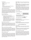
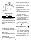
t = Span length, inches
C = Center distance, inches
D = Larger sheave diameter, inches
d = Smaller sheave diameter, inches
h = Deflection height, inches
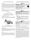
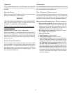
DRIVE BELT TENSION ADJUSTMENT
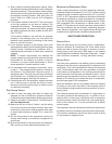
BELT DRIVE Used New
A, AX Standard 3.0 to 4.0 4.2 ± .5 5.5 ± .5 0.313
DEFLECTION
(in)
DEFLECTION
FORCE (lbs)
SHEAVE
DIAMETER
(in)
TYPE
RECOMMENDED POUNDS OF FORCE PER BELT
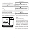
New V-belts will drop rapidly during the first few hours of use.
Check tension frequently during the first 24 hours of opera-
tion. Tension should fall between the minimum and maximum
force. To determine the deflection distance from a normal
position, measure the distance from sheave to sheave using
a straightedge or a cord. This is your reference line. On mul-
tiple belt drives, an adjacent undeflected belt can be used as
a reference.
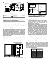
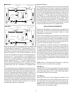
EVAPORATOR FAN ROTATION CHECK (THREE PHASE MODELS
ONLY)
Check that fan rotates counter-clockwise when viewed from
the drive side of unit and in accordance with rotation arrow
shown on blower housing. If it does not, reverse the two in-
coming power cables. In this case, repeat bearing check.
Do not attempt to change load side wiring. Internal wiring
assures all motors and compressors will rotate in correct di-
rection once evaporator fan motor rotation check has been
made.
ELECTRICAL INPUT CHECK
Make preliminary check of evaporator fan ampere draw and
verify that motor nameplate amps are not exceeded. A final
check of amp draw should be made upon completion of air
balancing of the duct system (see Appendix B).
REFRIGERATION SYSTEM CHECKS
Ensure the hold-down bolts on the compressor are secure
and have not vibrated loose during shipment. Check that vi-
bration grommets have been installed. Visually check all pip-
ing and clamps. The entire refrigeration system has been
factory charged and tested, making it unnecessary to field
charge. Factory charges are shown on the unit nameplate.
Install service manifold hoses. Gauges should read satura-
tion pressure corresponding to ambient temperature. Charge
should be checked to obtain 12° to 15° of sub-cooling per
system (i.e. compressor circuits).
START-UP PROCEDURE AND CHECKLIST
Begin with power turned off at all disconnects.
1. Turn thermostat system switch to “Cool,” and fan
switch to “Auto” and turn temperature setting as high
as it will go.
2. Inspect all registers and set them to the normal open
position.
3. Turn on the electrical supply at the disconnect.
4. Turn the fan switch to the “ON” position. The blower
should operate after a 7 second delay.
5. Turn the fan switch to “Auto” position. The blower
should stop after a 65 second delay.
6. Slowly lower the cooling temperature until the unit
starts. The compressor, blower and fan should now
be operating. Allow the unit to run 10 minutes, make
sure cool air is being supplied by the unit.
7. Turn the temperature setting to the highest position,
stopping the unit. The indoor blower will continue to
run for 65 seconds.
8. Turn the thermostat system switch to “OFF” and
disconnect all power when servicing the unit.
HIGH VOLTAGE!
D
ISCONNECT
ALL
POWER
BEFORE
SERVICING
OR
INSTALLING
THIS
UNIT
. M
ULTIPLE
POWER
SOURCES
MAY
BE
PRESENT
. F
AILURE
TO
DO
SO
MAY
CAUSE
PROPERTY
DAMAGE
,
PERSONAL
INJURY
OR
DEATH
.
WARNING
HEAT PUMP START-UP PROCEDURE
9. Check the cooling mode for the heat pump in the same
manner as above. The reversing valve is energized
when the thermostat is placed in the cooling position.
A clicking sound should be noticeable from the
reversing valve. By lowering the temperature setting
to call for cooling, the contractor is energized. The
compressor, blower and fan should then be running.
After the cooling mode is checked out, turn the
thermostat system switch to “OFF”.
10. Turn the thermostat system switch to “HEAT” and fan
switch to “AUTO”.