


10
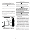
CIRCULATING AIR AND FILTERS
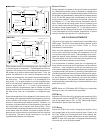
DUCTWORK
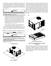
The supply duct from the unit through a wall may be installed
without clearance. However, minimum unit clearances must
be maintained (see “Clearances” section). The supply duct
should be provided with an access panel large enough to
inspect the air chamber downstream of the heat exchanger.
A cover should be tightly attached to prevent air leaks.
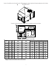
Ductwork dimensions are shown in the roof curb installation
manual.
If desired, supply and return duct connections to the unit may
be made with flexible connections to reduce possible unit
operating sound transmission.
VENTING
NOTE: Venting is self-contained.
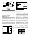
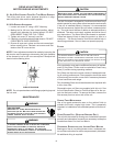
CONDENSATE DRAIN CONNECTION
CONDENSATE DRAIN CONNECTION
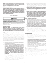
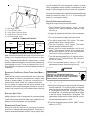
A 3/4” NPT drain connection is supplied for condensate pip-
ing. An external trap must be installed for proper condensate
drainage.
DRAIN
CONNECTION
UNIT 2" MINIMUM
FLEXIBLE
TUBING-HOSE
OR PIPE
3" MINIMUM
A POSITIVE LIQUID
SEAL IS REQUIRED
Drain Connection
Install condensate drain trap as shown. Use 3/4" drain line
and fittings or larger. Do not operate without trap.
HORIZONTAL DRAIN
Drainage of condensate directly onto the roof may be ac-
ceptable; refer to local code. It is recommended that a small
drip pad of either stone, mortar, wood or metal be provided to
prevent any possible damage to the roof.
CLEANING
Due to the fact that drain pans in any air conditioning unit
will have some moisture in them, algae and fungus will
grow due to airborne bacteria and spores. Periodic clean-
ing is necessary to prevent this build-up from plugging the
drain.
STARTUP, ADJUSTMENTS, AND CHECKS
HIGH VOLTAGE!
OND
THE
FRAME
OF
THIS
UNIT
TO
THE
BUILDING
ELECTRICAL
GROUND
BY
USE
OF
THE
GROUNDING
TERMINAL
PROVIDED
OR
OTHER
ACCEPTABLE
MEANS
. D
ISCONNECT
ALL
POWER
BEFORE
SERVICING
OR
INSTALLING
THIS
UNIT
.
T
O
AVOID
PERSONAL
INJURY
OR
DEATH
DUE
TO
ELECTRICAL
SHOCK
,
B
WARNING
PRE-STARTUP INSTRUCTIONS
T
O
PREVENT
PROPERTY
DAMAGE
OR
PERSONAL
INJURY
, D
O
NOT
START
THE
UNIT
UNTIL
ALL
NECESSARY
PRE
-
CHECKS
AND
TESTS
HAVE
BEEN
PERFORMED
.
CAUTION
Prior to the beginning of Startup, Adjustments, and Checks
procedures, the following steps should be completed in the
building.
THERMOSTAT. Set the thermostat in the conditioned
space at a point at least 10°F below zone temperature.
Set the thermostat system switch on COOL and the
fan switch on AUTO.
NIGHT SETBACK THERMOSTAT (OPTIONAL). Set
thermostat at a point at least 10°F below zone
temperature.
MOVING MACHINERY HAZARD!
T
O
PREVENT
POSSIBLE
PERSONAL
INJURY
OR
DEATH
,
DISCONNECT
POWER
TO
THE
UNIT
AND
PADLOCK
IN
THE
“OFF”
POSITION
BEFORE
SERVICNG
FANS
.
WARNING
HEATING STARTUP
On new installations, or if a major component has been re-
placed, the operation of the unit must be checked.
Check unit operation as outlined in the following instructions.
If any sparking, odors, or unusual sounds are encountered,
shut off electrical power and recheck for wiring errors, or ob-
structions in or near the blower motors. Duct covers must
be removed before operating unit.
The Startup, Adjustments, and Checks procedure provides a
step-by-step sequence which, if followed, will assure the
proper startup of the equipment in the minimum amount of
time. Air balancing of duct system is not considered part of
this procedure. However, it is an important phase of any air
conditioning system startup and should be performed upon
completion of the Startup, Adjustments, and Checks proce-
dure. The Startup, Adjustments, and Checks procedure at
outside ambients below 55°F should be limited to a readi-
ness check of the refrigeration system with the required final
check and calibration left to be completed when the outside
ambient rises above 55°F.