


14
E
V
A
P
O
R
A
T
O
R
COOLING
SERVICE VALVE
SERVICE PORT
REVERSING VALVE
C
O
N
D
E
N
S
E
R
SERVICE PORT
COMPRESSOR
SERVICE PORT
ACCUMULATOR
EXPANSION DEVICE
CHECK VALVE
ORIFICE
SERVICE
VALVE
CHECK VALVE
ORIFICE
INDOOR
COIL
DISTRIBUTOR
OUTDOOR
COIL
E
V
A
P
O
R
A
T
O
R
HEATING
SERVICE VALVE
SERVICE PORT
REVERSING VALVE
C
O
N
D
E
N
S
E
R
COMPRESSOR
SERVICE PORT
ACCUMULATOR
CHECK VALVE
ORIFICE
SERVICE
VALVE
CHECK VALVE
ORIFICE
INDOOR
COIL
DISTRIBUTOR
OUTDOOR
COIL
DISTRIBUTOR
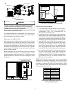
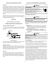
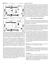
When the heat pump is on the heating cycle, the outdoor coil
is functioning as an evaporator. The temperature of the re-
frigerant in the outdoor coil must be below the temperature of
the outdoor air in order to extract heat from the air. Thus, the
greater the difference in the outdoor temperature and the
outdoor coil temperature, the greater the heating capacity of
the heat pump. This phenomenon is a characteristic of a
heat pump. It is a good practice to provide supplementary
heat for all heat pump installations in areas where the tem-
perature drops below 45° F. It is also a good practice to
provide sufficient supplementary heat to handle the entire
heating requirement should there be a component failure of
the heat pump, such as a compressor, or refrigerant leak,
etc.
Since the temperature of the refrigerant in the outdoor coil on
the heating cycle is generally below freezing point, frost forms
on the surfaces of the outdoor coil under certain weather con-
ditions of temperature and relative humidity. Therefore, it is
necessary to reverse the flow of the refrigerant to provide hot
gas in the outdoor coil to melt the frost accumulation. This is
accomplished by reversing the heat pump to the cooling cycle.
At the same time, the outdoor fan stops to hasten the tem-
perature rise of the outdoor coil and lessen the time required
for defrosting. The indoor blower continues to run and the
supplementary heaters are energized.
DEFROST CONTROL
During operation the power to the circuit board is controlled
by a temperature sensor, which is clamped to a feeder tube
entering the outdoor coil. Defrost timing periods of 30,60 and
90 minutes may be selected by setting the circuit board jumper
to 30, 60 and 90 respectively. Accumulation of time for the
timing period selected starts when the sensor closes (ap-
proximately 31° F), and when the wall thermostat calls for
heat. At the end of the timing period, the unit’s defrost cycle
will be initiated provided the sensor remains closed. When
the sensor opens (approximately 75° F), the defrost cycle is
terminated and the timing period is reset. If the defrost cycle
is not terminated due to the sensor temperature, a twelve
minute override interrupts the unit’s defrost period.
AIR FLOW ADJUSTMENTS
The drive on the supply fan is typically set in the middle of the
RPM range. The drive motor sheave pitch diameter is field
adjustable for the required airflow. Refer to “Drive
Adjustments” section below.
When the final adjustments are complete, the current draw
of the motor should be checked and compared to the full
load current rating of the motor. The amperage must not ex-
ceed the service factor stamped on the motor nameplate.
The total airflow must not be less than that required for op-
eration of the electric heaters or the furnace.
If an economizer is installed, check the unit operating bal-
ance with the economizer at full outside air and at minimum
outside air. Upon completion of the air flow balancing, we
recommend replacing the variable pitched motor sheave with
a properly-sized fixed sheave. A matching fixed sheave will
provide longer belt and bearing life and vibration free opera-
tion. Initially, it is best to have a variable pitched motor sheave
for the purpose of airflow balancing, but once the balance
has been achieved, fixed sheaves maintain alignment and
minimize vibration more effectively. For direct drive units, move
green wire for fan.
NOTE: Never run CFM below 350 CFM per ton, evaporator
freezing or poor unit performance is possible.
PSC MOTOR
Adjust the CFM for the unit by changing the speed tap of the
indoor blower motor at the EBTDR “com” connection with the
one of the speed taps on “M1” or “M2” (Black-High Speed,
Blue-Medium Speed, Red-Low Speed).
X-13 MOTOR
Adjust the CFM for the unit by changing the position of the
low voltage leads on the motor terminal block. Green is for
Fan Only. Yellow is for Cooling and Heat Pump Heating. Re-
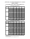
fer to Appendix A for blower performance at each speed tap.
NOTE: If more than one lead is energized simultaneously,
the motor will run at the higher speed.