


15
DRIVE ADJUSTMENTS
MOTOR SHEAVE ADJUSTMENTS
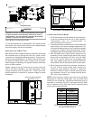
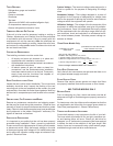
VL, VM, & 2VP VARIABLE PITCH KEY TYPE MOTOR SHEAVES
The driving and driven motor sheaves should be in align-
ment with each other and the shafts parallel.
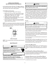
VL & VM SHEAVES ADJUSTMENT
1. Loosen set screw “B” using a 5/32" Allen key.
2. Making half or full turns from closed position, adjust
sheave pitch diameter for desired speed. DO NOT
OPEN MORE THAN FIVE FULL TURNS.
3. Tighten set screw “B” securely over flat.
4. Carefully put on belts and adjust belt tension. DO NOT
FORCE BELTS OVER GROOVES.
5. Ensure all keys are in place and the set screws tight
before starting drive. Recheck set screws and belt
tension after 24 hours service.
NOTE: Future adjustments should be made by loosening the
belt tension and increasing or decreasing the pitch diameter
of the sheave by half or full turns as required. Readjust belt
tension before starting drive.
C
B
VL & VM
SHEAVE DIAGRAM
NOTE: Do not operate sheave with flange projecting beyond
the hub end.
MAINTENANCE
HIGH VOLTAGE!
D
ISCONNECT
ALL
POWER
BEFORE
SERVICING
OR
INSTALLING
THIS
UNIT
. M
ULTIPLE
POWER
SOURCES
MAY
BE
PRESENT
. F
AILURE
TO
DO
SO
MAY
CAUSE
PROPERTY
DAMAGE
,
PERSONAL
INJURY
OR
DEATH
.
WARNING
T
O
PREVENT
PERSONAL
INJURY
OR
DEATH
DUE
TO
IMPROPER
INSTALLATION
,
ADJUSTMENT
,
ALTERATION
,
SERVICE
OR
MAINTENANCE
,
REFER
TO
THIS
MANUAL
. F
OR
ADDITIONAL
ASSISTANCE
OR
INFORMATION
,
CONSULT
A
QUALIFIED
INSTALLER
,
SERVICE
AGENCY
OR
THE
GAS
SUPPLIER
.
WARNING
S
HEET
METAL
PARTS
,
SCREWS
,
CLIPS
AND
SIMILAR
ITEMS
INHERENTLY
HAVE
SHARP
EDGES
,
AND
IT
IS
NECESSARY
THAT
THE
INSTALLER
AND
SERVICE
PERSONNEL
EXERCISE
CAUTION
.
CAUTION
The Self Contained Packaged Air Conditioner and Heat Pump
should operate for many years without excessive service calls
if the unit is installed properly. However it is recommended
that the homeowner inspect the unit before a seasonal start
up. The coils should be free of debris so adequate airflow is
achieved. The return and supply registers should be free of
any obstructions. The filters should be cleaned or replaced.
These few steps will help to keep the product up time to a
maximum. The Service section that follows should help in
identifying problems if the unit does not operate properly.
FILTERS
CAUTION
T
O PREVENT PROPERTY DAMAGE DUE TO FIRE AND LOSS OF
EQUIPMENT EFFICIENCY OR EQUIPMENT DAMAGE DUE TO DUST AND LINT
BUILD UP ON INTERNAL PARTS, NEVER OPERATE UNIT WITHOUT AN AIR
FILTER INSTALLED IN THE RETURN AIR SYSTEM.
Every application may require a different frequency of replace-
ment of dirty filters. Filters must be replaced at least every
three (3) months during operating seasons.
Dirty filters are the most common cause of inadequate heat-
ing or cooling performance. Filter inspection should be made
at least every two months; more often if necessary because
of local conditions and usage.
Dirty throwaway filters should be discarded and replaced with
a new, clean filter.
Disposable return air filters are supplied with this unit. See
the unit Specification Sheet or Technical Manual for the cor-
rect size and part number. To remove the filters, remove the
filter access panel on return side of the unit.
CABINET FINISH MAINTENANCE
Use a fine grade automotive wax on the cabinet finish to
maintain the finish’s original high luster. This is especially
important in installations with extended periods of direct sun-
light.
CLEAN OUTSIDE COIL (QUALIFIED SERVICER ONLY)
The coil with the outside air flowing over it should be inspected
annually and cleaned as frequently as necessary to keep the
finned areas free of lint, hair and debris.
CONDENSER, EVAPORATOR, AND INDUCED DRAFT MOTORS
Bearings on the air circulating blower motor, condenser mo-
tor and the combustion fan motor are permanently lubricated.
No additional oiling is required.