


8
T
O
PREVENT
SEVERE
DAMAGE
TO
THE
BOTTOM
OF
THE
UNIT
,
DO
NOT
FORK
LIFT
UNIT
AFTER
WOOD
STRUTS
HAVE
BEEN
REMOVED
.
CAUTION
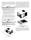
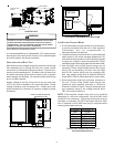
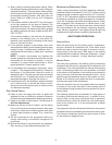
Bring condenser end of unit into alignment with the curb. With
condenser end of the unit resting on curb member and using
curb as a fulcrum, lower opposite end of the unit until entire
unit is seated on the curb. When a rectangular cantilever
curb is used, care should be taken to center the unit. Check
for proper alignment and orientation of supply and return open-
ings with duct.
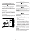
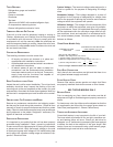
RIGGING REMOVAL
T
O
PREVENT
DAMAGE
TO
THE
UNIT
,
DO
NOT
ALLOW
CRANE
HOOKS
AND
SPREADER
BARS
TO
REST
ON
THE
ROOF
OF
THE
UNIT
.
CAUTION
Remove spreader bars, lifting cables and other rigging equip-
ment.
ELECTRICAL WIRING
HIGH VOLTAGE!
D
ISCONNECT
ALL
POWER
BEFORE
SERVICING
OR
INSTALLING
THIS
UNIT
. M
ULTIPLE
POWER
SOURCES
MAY
BE
PRESENT
. F
AILURE
TO
DO
SO
MAY
CAUSE
PROPERTY
DAMAGE
,
PERSONAL
INJURY
OR
DEATH
.
WARNING
HIGH VOLTAGE!
T
O
AVOID
PERSONAL
INJURY
OR
DEATH
DUE
TO
ELECTRICAL
SHOCK
,
DO
NOT
TAMPER
WITH
FACTORY
WIRING
. T
HE
INTERNAL
POWER
AND
CONTROL
WIRING
OF
THESE
UNITS
ARE
FACTORY
-
INSTALLED
AND
HAVE
BEEN
THOROUGHLY
TESTED
PRIOR
TO
SHIPMENT
.
C
ONTACT
YOUR
LOCAL
REPRESENTATIVE
IF
ASSISTANCE
IS
REQUIRED
.
WARNING
T
O
PREVENT
DAMAGE
TO
THE
WIRING
,
PROTECT
WIRING
FROM
SHARP
EDGES
. F
OLLOW
NATIONAL
ELECTRICAL
CODE
AND
ALL
LOCAL
CODES
AND
ORDINANCES
. D
O
NOT
ROUTE
WIRES
THROUGH
REMOVABLE
ACCESS
PANELS
.
CAUTION
C
ONDUIT
AND
FITTINGS
MUST
BE
WEATHER
-
TIGHT
TO
PREVENT
WATER
ENTRY
INTO
THE
BUILDING
.
CAUTION
For unit protection, use a fuse or HACR circuit breaker that is
in excess of the circuit ampacity, but less than or equal to the
maximum overcurrent protection device. DO NOT EXCEED
THE MAXIMUM OVERCURRENT DEVICE SIZE SHOWN
ON UNIT DATA PLATE.
All line voltage connections must be made through weather-
proof fittings. All exterior power supply and ground wiring
must be in approved weatherproof conduit.
The main power supply wiring to the unit and low voltage
wiring to accessory controls must be done in accordance with
these instructions, the latest edition of the National Electrical
Code (ANSI/NFPA 70), and all local codes and ordinances.
All field wiring shall conform with the temperature limitations
for Type T wire (63°F/35°C rise).
The unit is factory wired for the voltage shown on the unit’s
data plate. Refer to model nomenclature in Appendix D for
voltage requirement for your unit.
NOTE: If supply voltage is 208V, lead on primary of trans-
former must be moved from the 230V to the 208V tap. Refer
to wiring diagram on unit for details.
Main power wiring should be sized for the minimum wire
ampacity shown on the unit’s data plate. Size wires in accor-
dance with the ampacity tables in Article 310 of the National
Electrical Code. If long wires are required, it may be neces-
sary to increase the wire size to prevent excessive voltage
drop. Wires should be sized for a maximum of 3% voltage
drop.
CAUTION
T
O AVOID PROPERTY DAMAGE OR PERSONAL INJURY DUE TO FIRE, USE
ONLY COPPER CONDUCTORS.
L
ABEL
ALL
WIRES
PRIOR
TO
DISCONNECTION
WHEN
SERVICING
CONTROLS
. W
IRING
ERRORS
CAN
CAUSE
IMPROPER
AND
DANGEROUS
OPERATION
. V
ERIFY
PROPER
OPERATION
AFTER
SERVICING
.
CAUTION
NOTE: A weather-tight disconnect switch, properly sized for
the unit total load, must be field installed. An external field
supplied disconnect may be mounted on the exterior panel.
Ensure the data plate is not covered by the field-supplied
disconnect switch.
• Some disconnect switches are not fused. Protect the
power leads at the point of distribution in accordance
with the unit’s data plate.
• The unit must be electrically grounded in accordance
with local codes or, in the absence of local codes,
with the latest edition of the National Electrical Code
(ANSI-NFPA 70). A ground lug is provided for this
purpose. Size grounding conductor in accordance
with Table 250-95 of the National Electrical Code. Do
not use the ground lug for connecting a neutral
conductor.
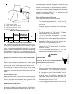
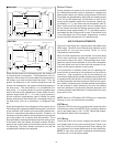
• Remove plug in panel located at the condenser end
of unit and route conduit to control box. Remove plug
in control box and connect power wiring to the
contactor closest to the entrance. If Single Point kit is
used, refer to Installation Instructions supplied with
kit.