


Installation of the range (cont.).
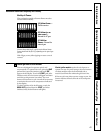
Provide Adequate Gas Supply
Your range is designed to operate at a pressure of 4
″
of water column on natural gas or, if designed for
LP gas (propane or butane), 10
″
of water column.
Make sure you are supplying your range with the
type of gas for which it is designed.
This range is convertible for use on natural or
propane gas. If you decide to use this range on LP
gas, conversion must be made by a qualified LP
installer before attempting to operate the range on
that gas.
For proper operation, the pressure of natural gas
supplied to the regulator must be between 4″ and
13″ of water column.
For LP gas, the pressure supplied must be between
10″ and 13″ of water column.
When checking for proper operation of the
regulator, the inlet pressure must be at least 1″
greater than the operating (manifold) pressure as
given above.
The pressure regulator located at the inlet of the
range manifold must remain in the supply line
regardless of whether natural or LP gas is being used.
A flexible metal appliance connector used to
connect the range to the gas supply line should have
an I.D. of 1/2″ and be 5 feet in length for ease of
installation. In Canada, flexible connectors must
be single wall metal connectors no longer than
6 feet in length.
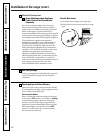
Connect the Range to Gas
Shut off the main gas supply valve before disconnecting the old range and leave it off until the new
hook-up has been completed. Don’t forget to relight the pilot on other gas appliances when you turn
the gas back on.
Because hard piping restricts movement of the
range, the use of an A.G.A.-certified flexible metal
appliance connector is recommended unless local
codes require a hard-piped connection.
Never use an old connector when installing a new
range. If the hard piping method is used, you must
carefully align the pipe; the range cannot be moved
after the connection is made.
To prevent gas leaks, put pipe joint compound on,
or wrap pipe thread tape with Teflon* around, all
male (external) pipe threads.
Install a manual gas line shut-off valve in the gas
line in an easily accessed location outside of the
range. Make sure everyone operating the range
knows where and how to shut off the gas supply
to the range.
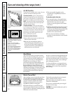
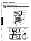
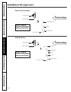
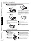
Install male 1/2″ flare union adapter to the
1/2″ NPT internal thread elbow at inlet of
regulator. On models equipped with standard
twin burners, install the male pipe thread end
of the 1/2″ flare union adapter to the 1/2″
NPT internal thread at inlet of pressure
regulator. Use a backup wrench on the
regulator fitting to avoid damage.
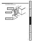
When installing the range from the front,
remove the 90° elbow for easier installation.
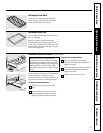
Install male 1/2″ or 3/4″ flare union adapter to
the NPT internal thread of the manual shut-off
valve, taking care to back-up the shut-off valve
to keep it from turning.
Connect flexible metal appliance connector to
the adapter on the range. Position range to
permit connection at the shut-off valve.
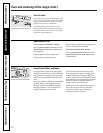
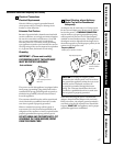
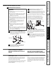
When all connections have been made,
make sure all range controls are in the off
position and turn on the main gas supply valve.
Use a liquid leak detector at all joints and
connections to check for leaks in the system.
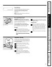
When using test pressures greater than 1/2 psig to
pressure test the gas supply system of the residence,
disconnect the range and individual shut-off valve
from the gas supply piping. When using test
pressures of 1/2 psig or less to test the gas supply
system, simply isolate the range from the gas supply
system by closing the individual shut-off valve.
*Teflon: Registered trademark of DuPont
CAUTION: DO NOT USE A FLAME TO
CHECK FOR GAS LEAKS.
Operating Instructions
Safety InstructionsInstallation InstructionsTroubleshooting TipsCustomer Service
44