


SmartCommand Thermostat
Installation Manual
26
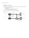
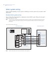
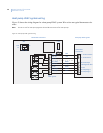
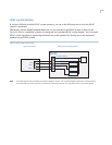
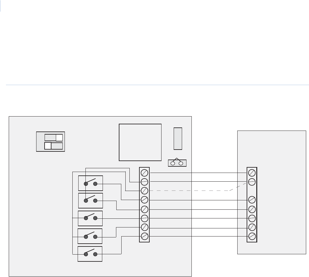
Heat pump HVAC system wiring
Figure 19 shows the wiring diagram for a heat pump HVAC system. Wire colors are typical thermostat color
codes.
Note: Do not cut JP1 for heat pump systems. RC and RH are common for heat pumps.
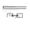
Figure 19. Heat pump HVAC system wiring
C 24 VAC common
R 24 VAC return
W1 Heat strips
O Changeover valve
G Fan
Y1 Comp stage 1
Y2 Comp stage 2
Thermostat
connections
Heat pump HVAC systemThermostat control unit
SW1
HP
STD 1
S2 2
OFF ON
J4
HVAC system
JP1
FUSE
24C COM
24V RH
24V RC
W1 Heat 1
W2/O CO
G Fan
Y1 Comp 1
Y2 Camp 2
Blue
Red
White
Orange
Green
Yellow
Black