


SmartCommand Thermostat
Installation Manual
22
Wall display unit installation
Choose a location for the wall display unit (WDU) that best represents the temperature of the area to be
controlled. Avoid locations that are subject to drafts or areas with direct sunlight exposure.
Mounting
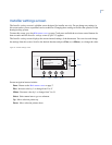
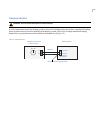
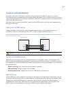
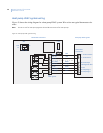
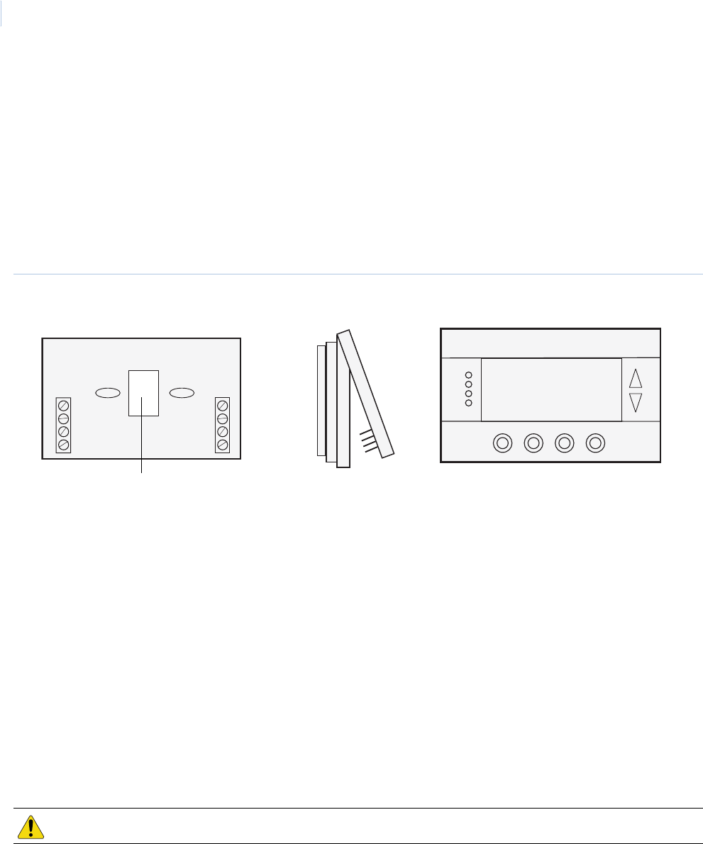
To mount the WDU, see Figure 16 and do the following:
1. To open the WDU case, pull from the lower corners of the case.
Figure 16. Opening and closing the WDU case
2. Route the wires to the WDU through the access hole in the back of the case (see Wiring).
3. Mount the WDU to the wall with the screws and anchors provided. Be sure to plug any large access
hole in the wall with sealer or insulation to prevent wall drafts from affecting WDU operation.
4. To close the case hook the top of the WDU and rotate into the base. Be sure pins engage in the
connector correctly
Wiring
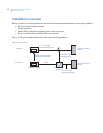
For new construction, we recommend you use a two twisted-pair cable, 22 Ga minimum, to the WDU from the
control unit. Category 5 wiring is preferred, but not required. In retrofit applications, the existing 18 Ga
thermostat wiring (at least four wires) is adequate and usually will work without problems. However, such
nontwisted wiring can be subject to interference due to adjacent in-wall high voltage wiring.
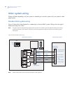
To wire the WDU to the control unit, connect the four-wire cable from the control unit to the WDU terminal
block. Two wires are for data and two are for power. WDU power is 12 VDC and provided by the control unit.
Remote sensor connection
The WDU base (Figure 16) has a remote sensor connection (J2) to connect an external remote temperature
sensor. Refer to the remote sensor documentation for the wiring diagram to connect the sensor to the WDU.
CAUTION: Do not miswire the power and data lines, damage will result. Check your wiring before applying power.
75
MODE
FAN
MENU
76 H
Econ
S
y
s Off
Run
No Msg
10:25
Outside 60
RUN
74 C
Front
Side view
Base
Wiring access hole
G
+5
C
D
J1
-
+
C
D
GND
+12V
Clock
Data
J2