25
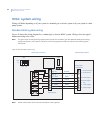
For standard HVAC systems, follow these guidelines:
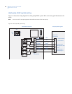
Single-stage systems. Use W1 for heating stage 1, and Y1 for cooling stage 1.
Two-stage heating systems. Use W1 for stage 1, and W2 for stage 2 heating.
Two-stage cooling systems. Use Y1 for stage 1 and Y2 for stage 2 cooling.
HVAC system 24 VAC transformer
If you have an integrated heating and cooling system with a single transformer, do not cut jumper JP1. Wire the
24V Return (red) wire to either RH or RC. This is typical of most central systems.
If you have separate heating and cooling systems with separate transformers, cut jumper JP1. Wire the heating
24V Return (red) wire to the control unit’s RH terminal and run the cooling system’s 24V Return (red) wire to
the control unit’s RC terminal. Wire the cooling system’s 24 VAC Com to the control unit’s 24 VAC Com
terminal. Do not connect the heating system’s common wire to the control unit.
DIP switches
To set the SW1 DIP switches for standard HVAC systems, do the following:
1. Set SW1-1 (position 1) to the Off (STD) position. This is the default setting.
2. Set SW1-2 (position 2) to the correct fan setting for your HVAC system.
• For gas furnaces that do not require fan output for heating operations, set SW1-2 to the Off
position (to the left). This is the default setting).
• For electric furnaces that do require fan output for heating operation, set SW1-2 to On position (to
the right).


