


9
Drain Line Connection
Note:
Standard commercial practices are expressed
here. Local codes may require changes to the following
suggestions. Check with local authorities before installing
a water conditioning system.
The system should be above, and not more than 20 feet
(6.1 m) from a drain. Connect an appropriate fitting and
1/2-inch (1.3-cm) plastic tubing to the drain line
connection on the rear of the control valve.
If the backwash flow is more than 5 gpm or if the unit is
located more than 20 feet (6.1 m) from the drain, use 3/4-
inch (1.9-cm) tubing for runs up to 40 feet (12.2 m). Also,
purchase appropriate fitting to connect the 3/4-inch
tubing to the 1/2-inch NPT drain connection.
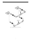
If unit is located where the drain line must be elevated, you
may elevate the line up to 5 feet (1.5 m) providing the run
does not exceed 15 feet (4.6 m) and water pressure at the
conditioners is not less than 40 psi (2.8 bar).
Where drain line is elevated but empties into a drain below
the level of the control valve, form a 7-inch (18-cm) loop at
the far end of the line so that the bottom of the loop is level
with the drain line connection. This will provide an
adequate siphon trap.Where a drain empties into an
overhead sewer line, a sink-type trap must be used. Secure
the end of the drain line to prevent it from moving
(Figure 11).
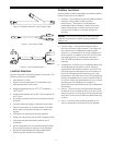
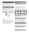
Brine Line Connection
It is recommended that separate brine lines be used for
each tank.
A regenerant tank aircheck is not required when using a
255 valve with the built-in aircheck. Doing so will cause
premature checking and may result in hard water or
regenerant tank overflow. The 255 aircheck is available
standard with a 1/4" NPT tube compression fitting. The
use of Teflon tape is required on the 1/4" NPT connection.
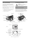
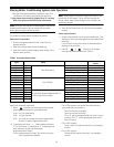
Install an appropriate fitting onto the 1/4-inch male NPT
connection on the air check (Figure 9), and install a length
of 3/8-inch polyethylene tubing between the air check
fitting and the brine pick-up tube at the brine tank. If you
are using a brine valve remove the ball in the air check to
avoid possible premature checking.
Figure 9
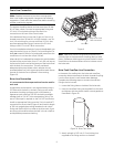
Note:
Make sure that all fittings and connections are
vacuum tight so that premature checking does not take
place. Premature checking occurs when the ball in the air
check falls to the bottom before all brine is drawn out of
the brine tank.
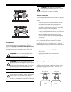
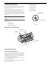
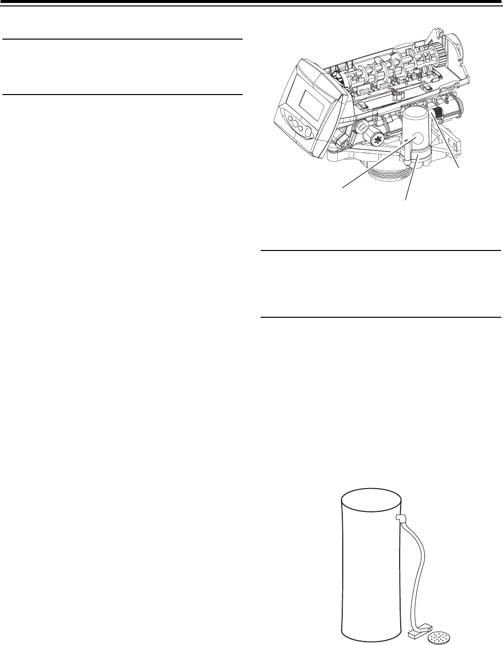
Brine Tank Overflow Line Connection
In the event of a malfunction, the brine tank overflow
connection directs overflow to the drain instead of spilling
it on the floor where it could cause water damage.
Complete the following steps to connect the overflow
fitting to the brine tank:
1. Locate the fitting hole on the side of the brine tank.
2. Insert the overflow fitting (not supplied) into the tank
and tighten with the plastic thumb nut and gasket as
illustrated in Figure 10.
Figure 10 Brine Tank Drain
3. Attach a length of 1/2-inch (1.3-cm) tubing (not
supplied) to the fitting and run to the drain.
Check Ball
Air Check
Regenerant Tank
Tube Connection