


10
Note:
Do not elevate the overflow line higher than
3 inches (7.6 cm) below the bottom of the overflow fitting.
Do not tie into the drain line of the control unit. The
overflow line must be a direct, separate line from the
overflow fitting to the drain, sewer, or tub. Allow an air gap
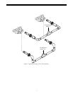
as in the drain line connection, Figure 10.
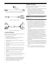
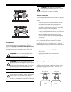
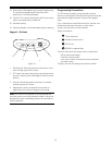
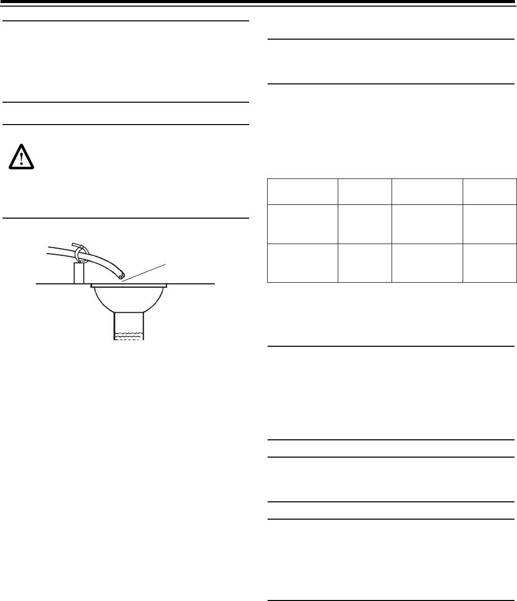
WARNING:
Never insert drain line directly into
a drain, sewer line, or trap (Figure 11). Always
allow an air gap between the drain line and the
waste water to prevent the possibility of sewage
being back-siphoned into the conditioner. Secure
the end of the drain line to prevent it from moving
(Figure 11).
Figure 11
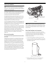
Brine Tank
Normally one brine tank is needed for each tank. The use
of block salt or rock salt is not recommended. If a brine
shelf is used, two brine tanks are required. This is due to the
increased time needed to produce a concentrated brine
solution when using a salt shelf. If rapid multiple
exhaustions and regenerations are anticipated, do not use
a salt shelf even if two brine tanks are used.
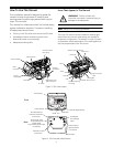
Electrical Connection
Caution:
This valve and control are for dry location use
only unless used with a Listed Class 2 power supply
suitable for outdoor use.
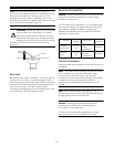
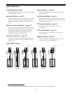
The 764 Series control operates on a 12-volt alternating
current power supply. This requires use of the GE Water
Technologies supplied AC adapter. A variety of AC
adapters are available from your supplier for different
applications. They include:
120 VAC AC Adapters:
Make sure power source matches the rating printed on the
AC adapter.
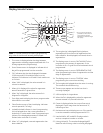
Note:
The power source should be constant. Be certain
the AC adapter is not on a switched outlet. Power
interruptions longer than 8 hours may cause the
controller to lose the time and day settings. When power
is restored, the control will display four dashes (- - :- -)
indicating that the day and time settings must be re-
entered
Note:
Do not connect power by plugging in the
transformer at this time. Doing so may cause difficulty in
properly placing the unit into operation.
Caution:
Plumbing cannot be used for electrical
grounding when metal inlet and outlet piping is
connected to a non-metal valve.
Connect the inlet and outlet piping together using a
grounding strap or clamp to establish continuity.
Drain
Air Gap
AC Adapter
Input
Voltage
Application
Part
Number
Standard
wall-mount
120V 60
Hz
UL listed for
indoor
installations
1000811
Outdoor
rated
120V 60
Hz
UL listed for
outdoor
installations
1235448