


8
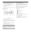
Figure 7
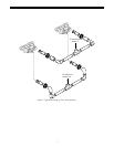
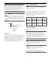
Installation
All plumbing must conform to local codes. The two tanks
should be plumbed to an interconnecting manifold,
Figure 6. It is highly recommended that separate brine
lines be used for each tank. It is critical for the resin, resin
volume, inlet piping, etc. to be identical for both tanks.
WARNING:
Do not use tools to tighten plastic
fittings. Over time, stress may break the
connections. Hand tighten the nuts.
WARNING:
Do not use petroleum grease on
gaskets when connecting bypass plumbing. Use
only 100% silicone grease products when
installing any Autotrol brand valve. Non-silicone
grease may cause plastic components to fail
over time.
WARNING:
The inlet water must be connected
to the inlet port of the valve. When replacing non-
Autotrol valves, the inlet and outlet may be
reversed. Ensure that the plumbing is not
installed in the oppposite order. Tank media may
be pushed into the valve.
WARNING:
Filter media may need to be
properly conditioned before the filter is placed
into full operation. Consult the original equipment
manufacturer for proper procedure.
Location Selection
The following considerations must be taken into account
when selecting the location for the water conditioning
system.
• Locate the system as close to a drain as possible.
• If supplementary water treating equipment is
required, make sure that adequate additional space
is available. Locate the brine tank in an accessible
place so that salt can be easily added.
• Do not install any system with less than 10 feet
(3 m) of piping between the outlet of the conditioners
and the inlet of the water heater. Water heaters can
transfer heat down the cold water pipe into the
control valve. Hot water can severely damage the
conditioners.
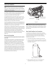
A ten-foot (3-m) total pipe run (including bends, elbows,
etc.) is a reasonable distance to prevent hot water
damage. A positive way to prevent hot water from flowing
from a heat source to the conditioners is to install an
expandable accumulator tank before the hot water heater.
Always conform to local codes.
• Do not locate the unit in an area where the ambient
temperature is ever below 34
o
F (1
o
C) or over
120
o
F (49
o
C).
• Maximum allowable water temperature is
100
o
F (38
o
C).
• Do not install the unit near acid or acid fumes.
• Do not expose the unit to petroleum products.
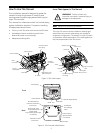
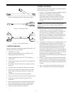
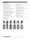
Water Line Connection
A bypass valve system must be installed to accommodate
occasions when the water conditioning system must be
bypassed for supplying hard water or servicing. See
Figures 7 and 8.
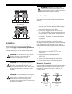
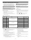
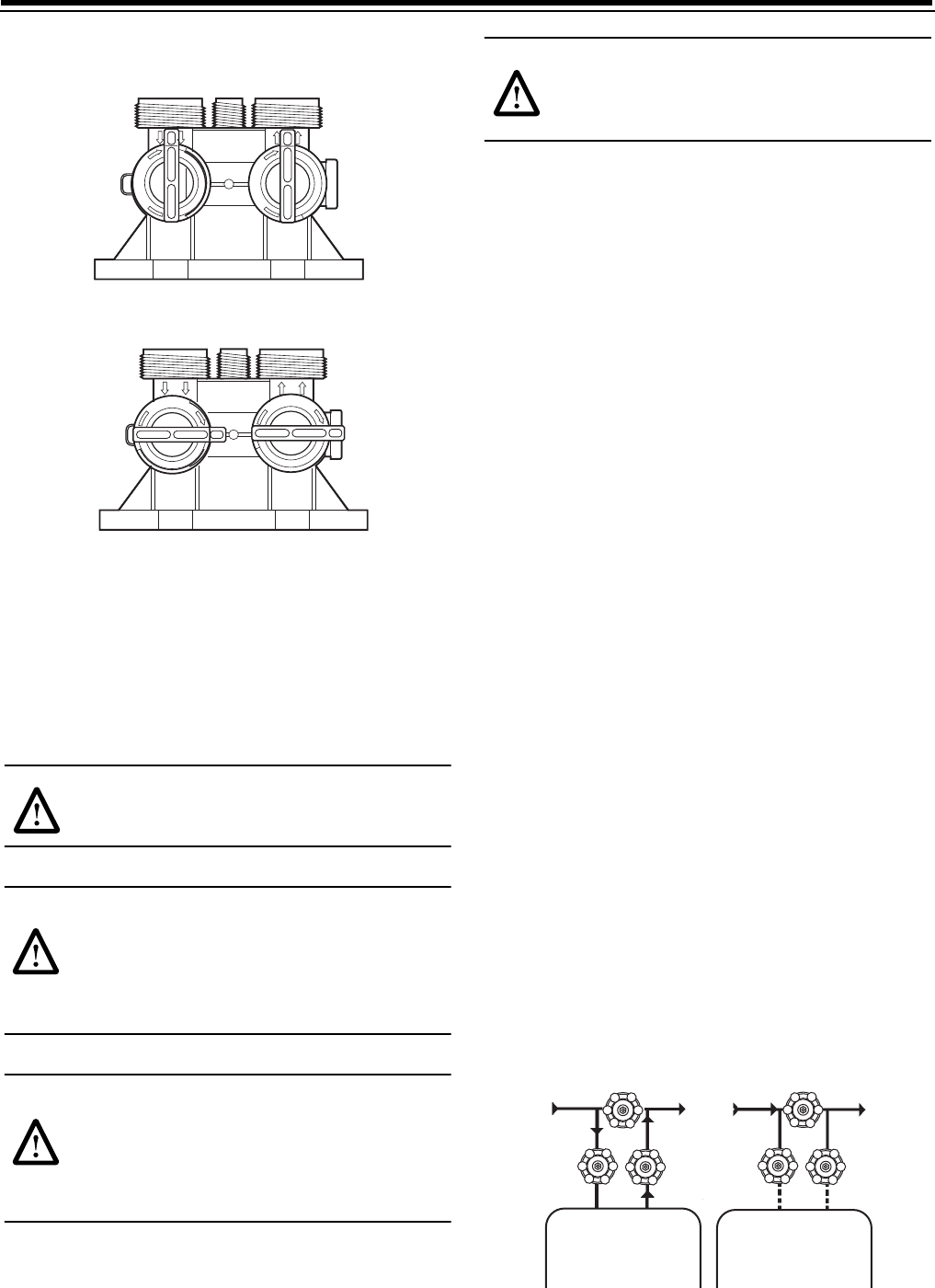
Figure 8
Unit in Bypass
Unit in Service
B
Y
P
A
S
S
B
Y
P
A
S
S
B
Y
P
A
S
S
B
Y
P
A
S
S
Wt
Wt
Conditioning
Conditioning
System
System
Not in Bypass
In Bypass