


29
Wiring Diagrams
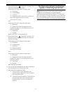
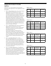
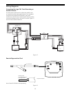
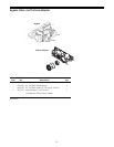
Connecting the Logix 764 Twin Alternating or
Parallel Controls
The twin sensor and extension cables are used for twin
unit parallel and alternating applications. Four standard
connections are required for operation; the power
transformer, the flow sensor, motor/optical sensor, and the
connection between tank 1 and tank 2 controls. Figure 15
outlines these standard features.
Figure 15
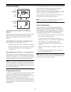
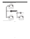
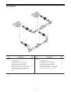
Remote Regeneration Start
Figure 16
P4
BL
BRN
WHT
YEL
ORG
P2
Flow Sensor
Optical
Sensor
Motor
80 in.
(2017 mm)
P3
2
BLK
GRN
R
Logix 764 control
on Tank 1
R
GRN
BLK
WHT
1
Flow Sensor
Optical
Sensor
Motor
BRN
ORG
WHT
YEL
BL
P1
Tank 1
Tank 2
Cut Cable here
Strip back insulation
Normally Open
Dry Contact Closure to
Start Regeneration
Note: Cable PN 3019464 sold separately.