


22
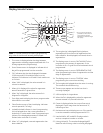
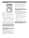
In Service Display
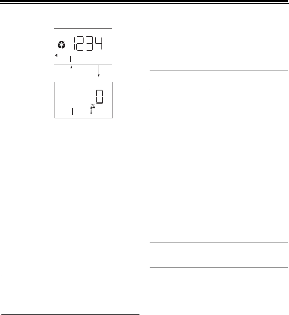
Logix 764 Electronic Multi-Tank - "A" Alternating
Control:
Service display — The number of the Tank in Service (small
digit next to CPH position) and Alternating Capacity
Remaining and Flow Rate with Faucet icon of Tank in
Service
Logix 764 Electronic Multi Tank - "P" Parallel Control:
Service Display — alternating three items
Capacity remaining for Tank 1 with digit "1" displayed
Capacity remaining for Tank 2 with digit "2" displayed
System Flow Rate (Tank 1 + Tank 2 added) with
Faucet icon
Logix 764 Electronic Multi Tank — "L" Lock Out Control
Service Display — Alternating Capacity Remaining and
Flow Rate with Faucet icon "L” displayed indicating lockout
signal is active. Blinking "L" and Lock icon if lockout signal
is active and control is ready to perform regeneration.
Note:
The faucet icon is displayed on all the Logix 764
controls when there is flow. The 764 will show the faucet
icon when the flow rate is displayed, even if the flow rate
is zero. If the flow rate is zero, the faucet will turn off when
the capacity is displayed.
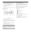
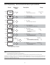
Programming Overview
The 764 control includes multiple program levels that allow
the Water Treatment Professional to customize the
system for many water conditions. Additionally, historical
data can be viewed allowing quick and easy
troubleshooting. In most cases Level I programming is all
that is required to set up the water conditioning system for
proper operation. A brief description of each program level
is listed below.
Level I Used to program control for normal applications.
Level II (P-Values) Allows the installer to customize
programming for non-standard applications.
Level Ill (C-Values) Allows the installer to adjust the length
of select cycles for non-standard applications.
Level IV History (H-Values) Allows access to historical
information for troubleshooting the system.
Note:
If a button is not pushed for thirty seconds, the
control returns to normal operation mode.
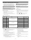
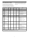
Level I Programming
The 764 control can be quickly programmed by
following the sequential procedure in the section
“Placing Water Conditioning System Into Operation”.
Level I program parameters are those that can be
accessed by pressing the UP or DOWN buttons.
• Resin Volume Setting: Set to match the volume (cubic
feet) of resin in the mineral tank.
• Time of Day: Includes PM indicator. Can be set to
display as a 24-hour clock. See Level ll programming
• Day of Week: Set to actual day of the week.
• Time of Regeneration: Fully adjustable. Default is
2:00 AM.
• Days Override: Range 0.5 to 99 days. Leave at 0 to
disable.
• Salt Dosage: Set at pounds of salt per cubic foot of
resin in the conditioner tank.
Note:
When the control is set up for a twelve-hour clock
a PM indicator will illuminate when the displayed time is in
the PM hours. There is no AM indicator.
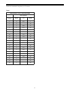
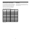
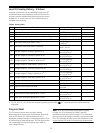
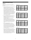
Time/Day
Regeneration Time
Salt Amount
SU MO TU WE TH FR SA DAYS
Capacity
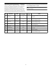
Time/Day
Regeneration Time
Salt Amount
SU MO TU WE TH FR SA DAYS
Capacity
Hardness
Hardness