


5
How To Use This Manual
This installation manual is designed to guide the
installer through the process of installing and
starting water conditioning systems featuring the
Logix 764 controller.
This manual is a reference and will not include every
system installation situation. The person installing
this equipment should have:
•
Training in the 764 series control and the 255 valve.
• Knowledge of water conditioning and how to
determine proper control settings.
• Adequate plumbing skills.
Icons That Appear In This Manual
WARNING:
Failure to follow this
instruction can result in personal injury or
damage to the equipment.
Note:
Helpful hint to simplify procedure.
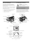
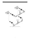
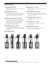
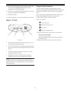
The Logix 764 control can be installed on several type
valves that can have twin alternating, twin parallel or
single tank configuration. The section on Logix 764 start-
up provides a simple explanation of the valve types that
are pre-programmed in the 764 control.
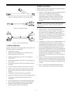
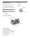
Figure 1 255 Valve Layout
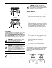
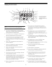
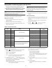
Figure 2 764 Controller Identification
Regenerant Tank
Tube Connection
Air Check
Check Ball
Injector
and Cap
Refill
Controller
Control Module
Optical Sensor
One Piece Valve
Disc Spring
Manifold
Connection
Valve Discs
Camshaft
Motor
Outlet
Drain
Inlet
Injector Screen
Filter
Locking Bar
Backwash Drain Control
Breakout Tabs for Wiring
Knockout Opening
for Wiring
Time/Day
Regeneration Time
Salt Amount
SU MO TU WE TH FR SA
g/L
PM
MIN
KG
x100
x2
P
H
C
Capacity
Hardness
Lbs/ft³
LCD Display
Manual Regen Button
Down Button
Set Button
Up Button
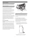
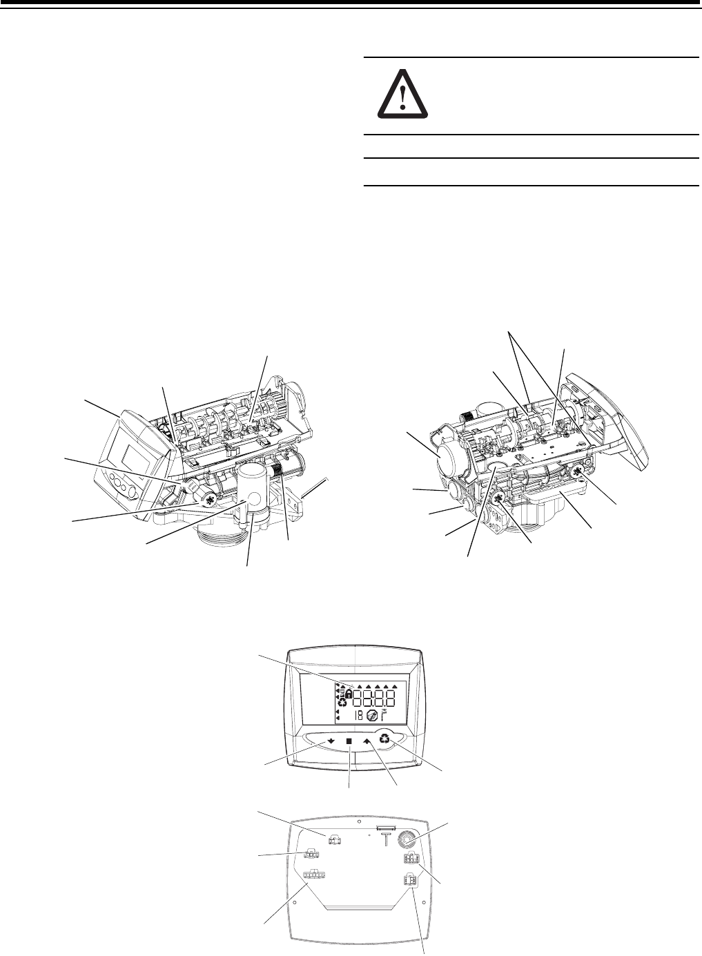
Turbine Input
Main Motor &
Optical Sensor
Connection
AC Adapter
(low voltage)
Input
Front
Back
Extension Cable
Connection
No-Salt Detector
(Chlorine Generator)
Connection
Lockout & Remote
Connection
Regen/Start
Multi Single Tank
Dry Contact Signal Input