


29
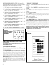
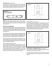
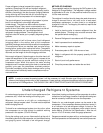
HEATING ELEMENT (See Figure 44)
All heat pumps and electric heat models are equipped with a
heating element with the exception of the YS09J10. The "YS",
"ES" and "EK12" models are equipped with a 3.3 KW element.
The "YM", "EM" and "EK18" models are equipped with a 4.0
KW element. The "YL" and "EL" models are equipped with a
5.2 KW element.
The heating element contains a fuse link and a heater limit
switch. The fuse link is in series with the power supply and will
open and interrupt the power when the temperature reaches
161.6°F, or a short circuit occurs in the heating element. Once
the fuse link separates, a new fuse link must be installed.
NOTE: Always replace with the exact replacement.
The heater element has a high limit control. This control is a
bimetal thermostat mounted in the top of the heating element.
Should the fan motor fail or filter become clogged, the high
limit control will open and interrupt power to the heater before
reaching an unsafe temperature condition.
The control is designed to open at 110°F ±6°F. Test continuity
below 110°F and for open above 110°F.
The heating element for the "Y" model is energized by an
outdoor thermostat. The outdoor thermostat is adjusted at a
predetermined temperature to bring on the heating element
and turn off the compressor. The room thermostat will then
control the cycling of the element when the selected indoor
temperature is reached.
Testing of the elements can be made with an ohmmeter across
the terminals after the connecting wires have been removed.
A cold resistance reading of approximately 14.5 ohms for the
3.3 KW heater, 11.9 ohms for the 4.0 KW heater and 9.15
ohms for the 5.2 KW heater should be registered.
SEALED REFRIGERATION SYSTEM REPAIRS
IMPORTANT
ANY SEALED SYSTEM REPAIRS TO HEAT PUMP
MODELS REQUIRES THE INSTALLATION OF A
SUCTION LINE DRIER IN THE SUCTION LINE
BETWEEN THE EVAPORATOR AND THE REVERSING
VALVE.
EQUIPMENT REQUIRED
1. Voltmeter
2. Ammeter
3. Ohmmeter
4. E.P.A. Approved Refrigerant Recovery System.
5. Vacuum Pump (capable of 200 microns or less vacuum.)
6. Acetylene Welder
7. Electronic Halogen Leak Detector (G.E. Type H-6 or
equivalent.)
8. Accurate refrigerant charge measuring device such as:
a. Balance Scales - 1/2 oz. accuracy
b. Charging Board - 1/2 oz. accuracy
9. High Pressure Gauge - (0 - 400 lbs.)
10. Low Pressure Gauge - (30 - 150 lbs.)
11. Vacuum Gauge - (0 - 1000 microns)
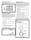
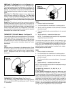
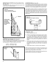
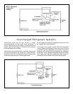
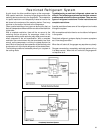
VALVE, DRAIN PAN (See Figure 43)
During the cooling mode of operation, condensate which
collects in the drain pan is picked up by the condenser fan
blade and sprayed onto the condenser coil. This assists in
cooling the refrigerant plus evaporating the water.
During the heating mode of operation, it is necessary that
water be removed to prevent it from freezing during cold
outside temperatures. This could cause the condenser fan
blade to freeze in the accumulated water and prevent it from
turning.
To provide a means of draining this water, a bellows type
drain valve is installed over a drain opening in the base pan.
This valve is temperature sensitive and will open when the
outside temperature reaches 40°F. The valve will close
gradually as the temperature rises above 40°F to fully close
at 60°F.
Figure 44 - Heating Element