


27
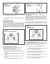
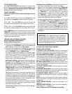
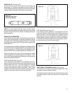
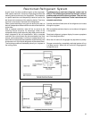
CHECK VALVE (See Figure 39)
A unique two-way check valve is used on the reverse cycle
heat pumps. It is pressure operated and used to direct the
flow of refrigerant through a single filter drier and to the proper
capillary tube during either the heating or cooling cycle
NOTE: The slide (check) inside the valve is made of teflon.
Should it become necessary to replace the check valve, place a
wet cloth around the valve to prevent overheating during the
brazing operation.
CHECK VALVE OPERATION
In the cooling mode of operation, high pressure liquid enters the
check valve forcing the slide to close the opposite port (liquid
line) to the indoor coil. Refer to refrigerant flow chart. This directs
the refrigerant through the filter drier and cooling capillary tube
to the indoor coil.
In the heating mode of operation, high pressure refrigerant enters
the check valve from the opposite direction, closing the port (liquid
line) to the outdoor coil. The flow path of the refrigerant is then
through the filter drier and heating capillary to the outdoor coil.
Failure of the slide in the check valve to seat properly in either
mode of operation will cause flooding of the cooling coil. This is
due to the refrigerant bypassing the heating or cooling capillary
tube and entering the liquid line.
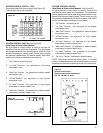
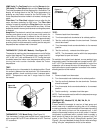
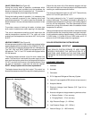
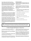
COOLING MODE (See Figure 40)
In the cooling mode of operation, liquid refrigerant from con-
denser (liquid line) enters the cooling check valve forcing the
heating check valve shut. The liquid refrigerant is directed
into the liquid dryer after which the refrigerant is metered
through cooling capillary tubes to evaporator. (Note: liquid
refrigerant will also be directed through the heating capillary
tubes in a continuous loop during the cooling mode).
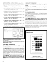
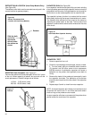
HEAT PUMPS: REVERSING VALVE (See Figure 42)
A reversing valve is used to change the refrigerant flow within
the system to permit heating or cooling.
The reversing valve consists of a main valve body which houses
the slide and piston, plus a pilot valve which is activated by a
solenoid.
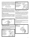
(TO INDOOR COIL)
(TO OUTDOOR COIL)
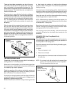
Figure 41
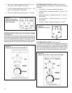
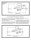
HEATING MODE (see Figure 41)
In the heating mode of operation, liquid refrigerant from the
indoor coil enters the heating check valve forcing the cooling
check valve shut. The liquid refrigerant is directed into the
liquid dryer after which the refrigerant is metered through the
heating capillary tubes to outdoor coils. (Note: liquid refriger-
ant will also be directed through the cooling capillary tubes in
a continuous loop during the heating mode).
(TO INDOOR COIL)
(TO OUTDOOR COIL)
Figure 40
Figure 39
One-way Check Valve
(Heat Pump Models)