


18
1. "Hi Cool" Turns on the compressor and fan at high speed
2. "Lo Cool" Turns on the compressor and fan at low speed.
3. "Fan Only" Turns on the fan at high speed.
4. "Off" Turns everything off.
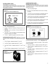
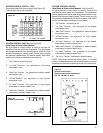
The switching arrangement of the control is as follows:
(See Figure 17)
1. "Off" All contacts open.
2. "Hi Fan
Contacts closed between terminals "L1" and
"1".
3. "Hi Cool" Contacts closed between terminals "L1" to "1"
and "L1" and "C".
4. "Lo-Cool" Contacts are closed between terminals "L1"
to "2" and "L1 to "C".
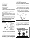
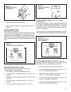
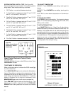
SYSTEM CONTROL PANEL ("YQ" Model Only)
(See Figure 14)
The YQ Model unit uses a six position control switch to regulate
the operation of the unit. Function of each position (Clockwise
rotation) is as follows:
1. "Off" - Turns everything off.
2. "Fan Only" - To circulate filtered room air, but no cooling
or heating.
3. "Hi Cool" - Fan runs continuously, compressor goes on
and off to maintain the selected room temperature.
4. "Lo Cool" - Fan runs continuously, compressor goes on
and off to maintain the selected room temperature.
5. "Lo Heat" - Fan Runs continuously, heating turns on and
off to maintain the selected room temperature.
6. "Hi Heat" - Fan Runs continuously, heating turns on and
off to maintain the selected room temperature.
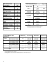
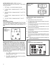
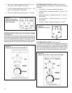
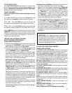
SYSTEM CONTROL SWITCH - TEST (See Figure 15)
Turn knob to phase of switch to be tested. There must be
continuity as follows:
1. "Fan Only" Position - between terminals "C" and "1".
2. "Hi Cool" Position - between terminals "C" and "1", "C"
and "3".
3. "Lo Cool" Position - between terminals "C" and "2", and
"C" and "3".
Figure 14
System Control Panel (YQ Model Only)
Figure 15
System Control Switch
(YQ Model Only)
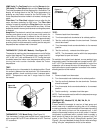
L1
MS
2
H
LO
C
L2
B1
Figure 13
System Control Switch
(EQ Models)
4. "Lo Heat" Position - between terminals "C" and "2", and
"C" and "4".
5. "Hi Heat" Position - between terminals "C" and "1", and
"C" and "4".
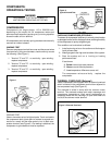
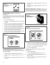
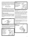
ROTARY (SYSTEM) SWITCH: "SC" Model (See Figure 16)
A rotary four position switch is used to turn on the unit and
select the operation desired. Switch selection is as follows:
Figure 16
System Control Panel (SC Model Only)