


25
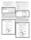
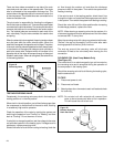
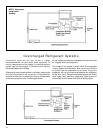
DEFROST THERMOSTAT (Heat Pump Models Only)
(See Figure 35)
This thermostat is single pole - double throw with contacts
between terminals "2" and "3" closing on temperature rise
and contacts between terminals "2" and "1" closing on
temperature fall. When the contacts between terminals "2"
and "1" make, power is supplied to the heater element.
This control is dual purpose control that acts as an outdoor
thermostat and defrost control.
When the sensing bulb, attached to the condenser coil, senses
enough icing on the outdoor coil, it will interrupt power to the
compressor and supply power to the heating element until
the coil temperature reaches above 43°, then the heater will
shut off and the unit will resume operating in the reverse cycle
mode.
When the outdoor coil temperature drops below 20°, the unit
will operate in electric heat mode continuously until the outdoor
coil temperature rises above 43°.
The fan motor will not turn off when defrost occurs, and the 4-
way valve will not reverse.
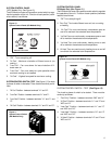
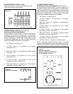
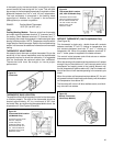
Figure 32
Thermostat
In the heating cycle, the heat anticipator is energized to supply
a small amount of heat during the "on" cycle. This will open
the contacts in the thermostat prematurely to maintain a closer
differential between the "cut in" and "cut out" temperature.
The heat anticipator is energized in the heating mode
regardless of whether fan is placed in the automatic
(MoneySaver) or constant run position.
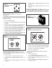
RANGE: Cooling Model Thermostat
60°F (±2°) to 92°F (±4°),
TEST:
Cooling/Heating Models: Remove wires from thermostat
and check continuity between terminal "2" (common) and "3"
for cooling. Check between terminals "2" (common) and "1"
for heating. Also check that contacts in thermostat open after
placing in either position. NOTE: Temperature must be within
range listed to check thermostat. Refer to the troubleshooting
section in this manual for additional information on thermostat
testing.
THERMOSTAT ADJUSTMENT
No attempt should be made to adjust thermostat. Due to the
sensitivity of the internal mechanism and the sophisticated
equipment required to check the calibration, it is suggested
that the thermostat be replaced rather than calibrated.
Thermostat bulb must be straight to insure proper
performance.
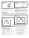
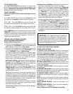
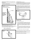
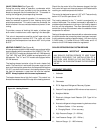
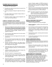
THERMOSTAT BULB LOCATION
The position of the bulb is important in order for the thermostat
to function properly. The bulb of the thermostat should be
located approximately 45° to a maximum of 60° from
horizontal. Also, do not allow the thermostat bulb to touch the
evaporator coil. (See Figures 33 and 34)
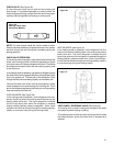
Thermostat sensor holder
020 to be positioned between
the 4th and 5th and 6th and
7th rows of tubes from the
bottom of the coil at
dimension shown
Figure 34
Thermostat Bulb Location
(KQ, YQ & SC Models Only)
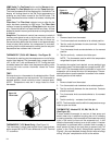
Thermostat sensor holder
020 and anticipator
(4712D-140) to be
positioned between the
4th and 5th and 6th and
7th rows of tubes from
the bottom of the coil at
dimension shown
Figure 33
Thermostat Bulb Location
(SQ Models Only)
Figure 35
Defrost Thermostat
(Heat Pump Models)