


26
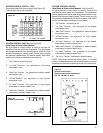
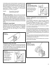
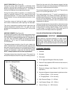
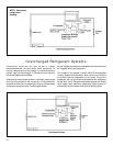
CAPACITOR, RUN (See Figure 38)
A run capacitor is wired across the auxiliary and main winding
of a single phase permanent split capacitor motor such as the
compressor and fan motor. A single capacitor can be used for
each motor or a dual rated capacitor can be used for both.
The capacitor's primary function is to reduce the line current
while greatly improving the torque characteristics of a motor.
The capacitor also reduces the line current to the motor by
improving the power factor of the load. The line side of the
capacitor is marked with a red dot and is wired to the line side
of the circuit.
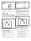
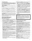
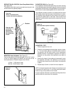
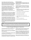
DEFROST BULB LOCATION (Heat Pump Models Only)
(See Figure 36)
The defrost control bulb must be mounted securely and in the
correct location to operate properly.
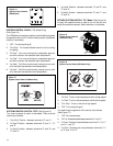
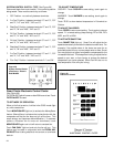
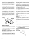
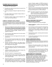
RESISTOR: Heat Anticipator (See Figure 37)
Failure of the resistor will cause prolonged "off" and "on" cycles
of the unit. When replacing a resistor, be sure and use the
exact replacement. Resistor ratings are as follows:
115 Volt - 5,000 ohms 3 watt
230 Volt - 20,000 ohms 3 watt
Figure 37
Resistor
Slide the bulb
end of the
thermostat
defrost under
the retainer as
shown
Retainer
Figure 36
Defrost Thermostat Bulb
Location (All Heat Pump Models)
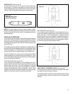
CAPACITOR - TEST
1. Remove capacitor from unit.
2. Check for visual damage such as bulges, cracks, or leaks.
3. For dual rated, apply an ohmmeter lead to common
(C) terminal and the other probe to the compressor
(HERM) terminal. A satisfactory capacitor will cause a
deflection on the pointer, then gradually move back to
infinity.
4. Reverse the leads of the probe and momentarily touch
the capacitor terminals. The deflection of the pointer
should be two times that of the first check if the capacitor
is good.
5. Repeat steps 3 and 4 to check fan motor capacitor.
NOTE: A shorted capacitor will indicate a low resistance and
the pointer will move to the "0" end of the scale and remain
there as long as the probes are connected.
An open capacitor will show no movement of the pointer when
placed across the terminals of the capacitor.
Figure 38
Dual Rated Run Capacitor Hook-up