


15
1. With no power to unit, remove the leads from the com-
pressor terminals.
2. Using an ohmmeter, test continuity between terminals
C-S and C-R. If no continuity, the compressor overload
is open and the compressor must be replaced.
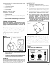
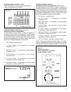
FAN MOTOR
A single phase permanent split capacitor motor is used to drive
the evaporator blower and condenser fan. A self-resetting over-
load is located inside the motor to protect against high tem-
perature and high amperage conditions. (See Figure 5)
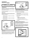
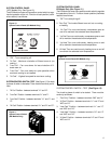
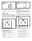
CHECKING THE INTERNAL OVERLOAD
(See Figure 4)
Heat generated within the compressor shell is usually due to:
1. High amperage
2. Low refrigerant charge
3. Frequent recycling
4. Dirty condenser
TERMINAL OVERLOAD - TEST
(Compressor - External Type)
1. Remove overload.
2. Allow time for overload to reset before attempting to
test.
3. Apply ohmmeter probes to terminals on overload wires.
There should be continuity through the overload.
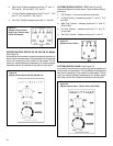
TERMINAL OVERLOAD (Internal)
Some model compressors are equipped with an internal
overload. The overload is embedded in the motor windings
to sense the winding temperature and/or current draw. The
overload is connected in series with the common motor
terminal.
Should the internal temperature and/or current draw become
excessive, the contacts in the overload will open, turning off
the compressor. The overload will automatically reset, but
may require several hours before the heat is dissipated.
Figure 4
Internal Overload
FAN MOTOR - TEST
1. Determine that capacitor is serviceable.
2. Disconnect fan motor wires from fan speed switch or
system switch.
3. Apply "live" test cord probes on black wire and common
terminal of capacitor. Motor should run at high speed.
4. Apply "live" test cord probes on red wire and common
terminal of capacitor. Motor should run at low speed.
5. Apply "live" test cord probes on each of the remaining
wires from the speed switch or system switch to test
intermediate speeds. If the control is in the
"MoneySaver" mode and the thermostat calls for
cooling, the fan will start - then stop after approximately
2 minutes; then the fan and compressor will start
together approximately 2 minutes later.
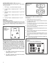
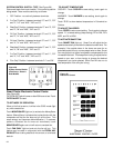
SYSTEM CONTROL PANEL- SQ Models (See Figure 6)
A five-position control switch is used to regulate the operation
of the fan motor and compressor. The compressor can be
operated with the fan operating at low, medium or high speed.
The fan motor can also be operated independently on medium
speed. See switch section as indicated on the decorative
control panel.
Figure 5
Fan Motor
Figure 6
System Control Panel (SQ Models Only)