


28
TESTING REVERSING VALVE
Occasionally, the reversing valve may stick in the heating or
cooling position or in the mid-position.
When stuck in the mid-position, part of the discharge gas from
the compressor is directed back to the suction side, resulting
in excessively high suction pressure.
Check the operation of the valve by starting the system and
switching the operation from "Cooling" to "Heating" and then
back to "Cooling". Do not hammer on valve.
If valve fails to change its position, test the voltage to the valve
coil while the system is in the heating cycle. If voltage to coil is
satisfactory, replace reversing valve.
Should the valve fail to shift from cooling to heating, block the
air flow through the outdoor coil and allow the discharge
pressure to build in the system. Then switch the system from
heating to cooling.
If the valve is stuck in the heating position, block the air flow
through the indoor coil and allow discharge pressure to build
in the system. Then switch the system from heating to cooling.
Should the valve fail to shift in either position after increasing
the discharge pressure, replace the valve.
NOTE: When brazing a reversing valve into the system, it is
of extreme importance that the temperature of the valve does
not exceed 250° F at any time.
Wrap the reversing valve with a large rag saturated with water.
"Re-wet" the rag and thoroughly cool the valve after each
brazing operation of the four joints involved.
The wet rag around the reversing valve will eliminate
conduction of heat to the valve body when brazing the line
connection.
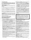
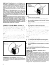
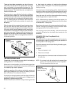
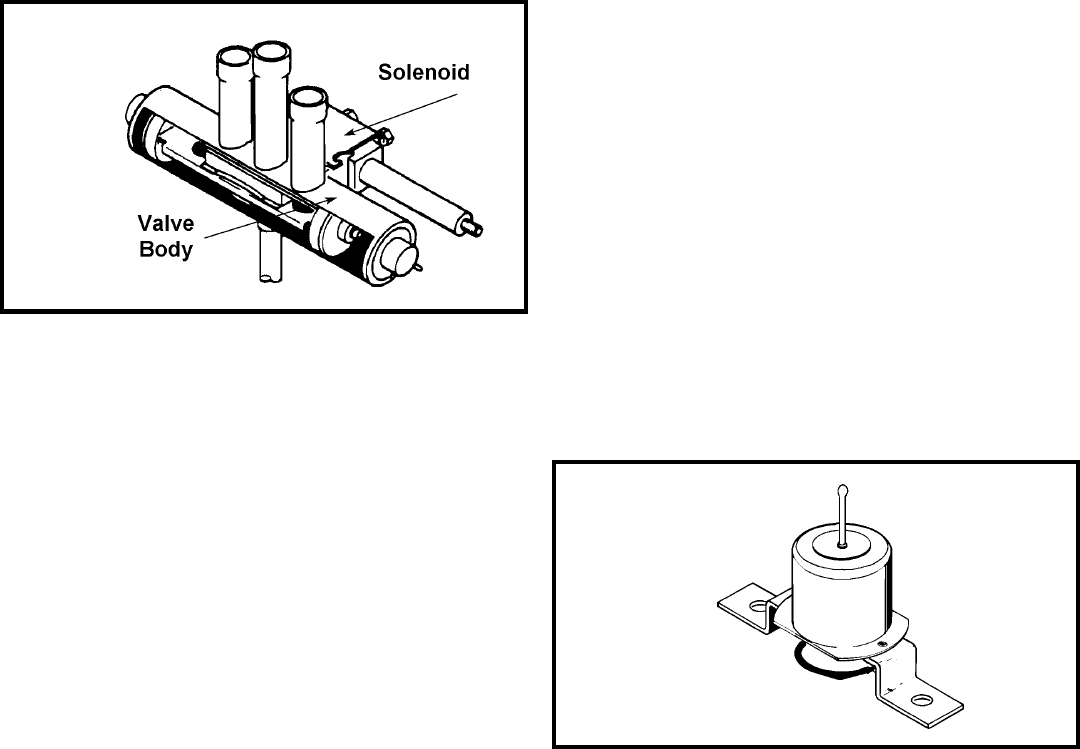
SOLENOID COIL (Heat Pump Models Only)
(See Figure 42)
The solenoid coil is an electromagnetic type coil mounted on
the reversing valve and is energized during the operation of
the compressor in the heating cycle.
Should the reversing valve fail to shift during the heating cycle,
test the solenoid coil.
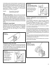
TO TEST:
1. Disconnect power to unit.
2. Disconnect coil leads.
3. Attach probes of an ohmmeter to each coil lead and check
for continuity.
NOTE: Do not start unit with solenoid coil removed from
valve, or do not remove coil after unit is in operation.
This will cause the coil to burn out.
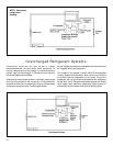
There are three tubes connected to one side of the main
valve body and one tube on the opposite side. The single
tube is connected to the compressor discharge line. The
center tube on the opposite side is the common suction line
to the compressor. The outside tubes are connected to the
indoor and outdoor coils.
The pivot valve is responsible for directing the refrigerant
flow to the indoor or outdoor coil. There are three small tubes
connected to the pilot valve body. The center pilot tube is the
common pilot tube and is connected to the center suction
line. The outside tubes are connected to each end of the
main valve body. The pilot valve consists of a needle valve
and spring.
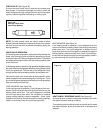
When the solenoid is de-energized, the spring tension closes
one pilot port while the other remains open. When the
solenoid is energized, the opposite end is closed. The piston
in the main valve is pressure operated and will always travel
in the direction of the open pilot tube port which provides a
path to the center tube. Pressure which will increase in the
opposite side of the valve will escape through a bleed port
located in each piston. When de-energized, the valve will be
in the cooling position.
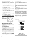
Figure 42
Reversing Valve
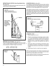
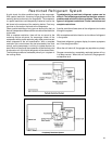
Figure 43
Bellows Assembly
Drain Pan Valve