


AN-2030: Digital Diagnostic Monitoring Interface for Optical Transceivers F i n i s a r
9/26/02 Revision D Page 32
Within the bus specifications a regular mode (100 kHz clock rate) and a fast mode (400
kHz clock rate) are defined. The DDTC works in both modes.
5) Acknowledge: Each receiving device, when addressed, is obliged to generate an
Acknowledge after the reception of each byte. The master device must generate an
extra clock pulse which is associated with this acknowledge bit.
A device that acknowledges must pull down the SDA line during the acknowledge clock
pulse in such a way that the SDA line is a stable LOW during the HIGH period of the
Acknowledge related clock pulse. Of course, setup and hold times must be taken into
account. A master must signal an end of data to the slave by not generating an
acknowledge bit on the last byte that has been clocked out of the slave. In this case, the
slave must leave the data line HIGH to enable the master to generate the STOP
condition.
1. Data transfer from a master transmitter to a slave receiver. The first byte transmitted
by the master is the command/control byte. Next follows a number of data bytes.
The slave returns an acknowledge bit after each received byte.
2. Data transfer from a slave transmitter to a master receiver. The master transmits the
1
st
byte (the command/control byte) to the slave. The slave then returns an
acknowledge bit. Next follows a number of data bytes transmitted by the slave to the
master. The master returns an acknowledge bit after all received bytes other than
the last byte. At the end of the last received byte, a ‘not acknowledge’ can be
returned.
The master device generates all serial clock pulses and the START and STOP
conditions. A transfer is ended with a STOP condition or with a repeated START
condition. Since a repeated START condition is also the beginning of the next serial
transfer, the bus will not be released.
The DDTC may operate in the following two modes:
1. Slave receiver mode: Serial data and clock are received through SDA and SCL
respectively. After each byte is received, an acknowledge bit is transmitted. START
and STOP conditions are recognized as the beginning and end of a serial transfer.
Address recognition is performed by hardware after reception of the slave (device)
address and direction bit.
2. Slave transmitter mode: The first byte is received and handled as in the slave
receiver mode. However, in this mode the direction bit will indicate that the transfer
direction is reversed. Serial data is transmitted on SDA by the DDTC while the serial
clock is input on SCL. START and STOP conditions are recognized as the beginning
and end of a serial transfer.
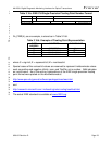
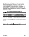
Slave Address: The command/control byte is the 1
st
byte received following the START
condition from the master device. The command/control byte consists of a 4-bit control
code. For the DDTC, this is set as 1010 000 binary for read/write operations. The last bit