


AN-2030: Digital Diagnostic Monitoring Interface for Optical Transceivers F i n i s a r
9/26/02 Revision D Page 22
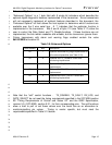
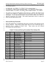
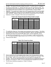
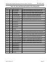
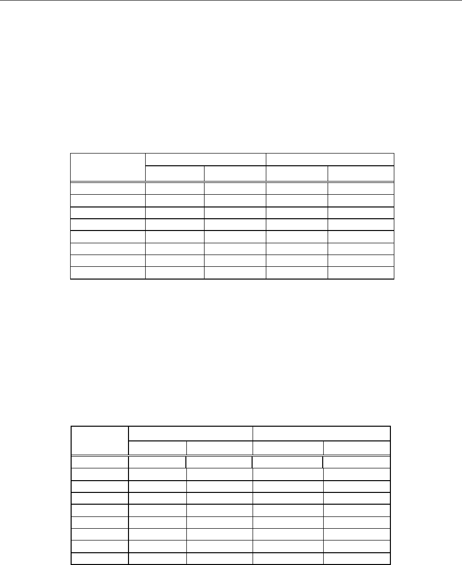
The slope constants at addresses 76, 80,84, and 88, are unsigned fixed-point binary 1
numbers. The slope will therefore always be positive. The binary point is in between 2
the upper and lower bytes, i.e., between the eight and ninth most significant bits. The 3
most significant byte is the integer portion in the range 0 to +255. The least significant 4
byte represents the fractional portion in the range of 0.00391 (1/256) to 0.9961 5
(255/256). The smallest real number that can be represented by this format is 0.00391 6
(1/256); the largest real number that can be represented using this format is 255.9961 7
(255 + 255/256). Slopes are defined, and conversion formulas found, in the “External 8
Calibration” section. Examples of this format are illustrated below: 9
10
Table 3.16a: Unsigned fixed-point binary format for slopes 11
12
Binary Value Hexadecimal Value
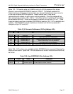
Decimal
Value
MSB LSB High Byte Low Byte
0.0000 00000000 00000000 00 00
0.0039 00000000 00000001 00 01
1.0000 00000001 00000000 01 00
1.0313 00000001 00001000 01 08
1.9961 00000001 11111111 01 FF
2.0000 00000010 00000000 02 00
255.9921 11111111 11111110 FF FE
255.9961 11111111 11111111 FF FF
13
14
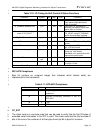
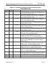
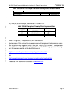
The calibration offsets are 16-bit signed twos complement binary numbers. The offsets 15
are defined by the formulas in the “External Calibration” section. The least significant bit 16
represents the same units as described above under “Internal Calibration” for the 17
corresponding analog parameter, e.g., 2µA for bias current, 0.1µW for optical power, 18
etc. The range of possible integer values is from +32767 to -32768. Examples of this 19
format are shown below. 20
21
22
Table 3.16b: Format for offsets 23
Binary Value Hexadecimal Value
Decimal
Value
High Byte Low Byte High Byte Low Byte
+32767 01111111 1111111 7F FF
+3 00000000 00000011 00 03
+2 00000000 00000010 00 02
+1 00000000 00000001 00 01
0 00000000 00000000 00 00
-1 11111111 11111111 FF FF
-2 11111111 11111110 FF FE
-3 11111111 11111101 FF FD
-32768 10000000 00000000 80 00
24
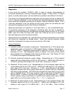
External calibration of received optical power makes use of single-precision floating-25
point numbers as defined by IEEE Standard for Binary Floating-Point Arithmetic, IEEE 26
Std 754-1985. Briefly, this format utilizes four bytes (32 bits) to represent real 27
numbers. The first and most significant bit is the sign bit; the next eight bits indicate an 28
exponent in the range of +126 to –127; the remaining 23 bits represent the mantissa. 29
The 32 bits are therefore arranged as in Table 3.16c below. 30