


AN-2030: Digital Diagnostic Monitoring Interface for Optical Transceivers F i n i s a r
9/26/02 Revision D Page 31
Detailed 2-Wire Serial Port Operation
This section gives a more detailed description of 2-wire theory of operation.
The 2-wire serial port interface supports a bi-directional data transmission protocol with
device addressing. A device that sends data on the bus is defined as a transmitter, and
a device receiving data as a receiver. The device that controls the message is called a
“master.” The devices that are controlled by the master are “slaves”. The bus must be
controlled by a master device that generates the serial clock (SCL), controls the bus
access, and generates the START and STOP conditions. The DDTC operates as a
slave on the two-wire bus. Connections to the bus are made via the open-drain I/O lines
SDA and SCL already described. The following I/O terminals control the 2-wire serial
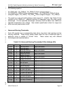
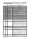
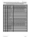
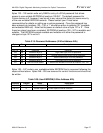
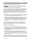
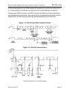
port: SDA and SCL. Timing diagrams for the 2-wire serial port can be found in Figure 1
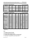
and 2 below. Timing information for the 2-wire serial port is provided in the AC Electrical
Characteristics table for 2-wire serial communications at the end of this section.
The following bus protocol has been defined:
§ Data transfer may be initiated only when the bus is not busy.
§ During data transfer, the data line must remain stable whenever the clock line is
HIGH. Changes in the data line while the clock line is HIGH will be interpreted as
control signals.
Accordingly, the following bus conditions have been defined:
1) Bus not busy: Both data and clock lines remain HIGH.
2) Start data transfer: A change in the state of the data line from HIGH to LOW while the
clock is HIGH defines a START condition.
3) Stop data transfer: A change in the state of the data line from LOW to HIGH while the
clock line is HIGH defines the STOP condition.
4) Data valid: The state of the data line represents valid data when, after a START
condition, the data line is stable for the duration of the HIGH period of the clock signal.
The data on the line can be changed during the LOW period of the clock signal. There is
one clock pulse per bit of data. Figures 1 and 2 detail how data transfer is accomplished
on the two-wire bus. Depending upon the state of the R/W bit, two types of data transfer
are possible.
Each data transfer is initiated with a START condition and terminated with a STOP
condition. The number of data bytes transferred between START and STOP conditions
are not limited and are determined by the master device. The information is transferred
byte-wise and each receiver acknowledges with a 9
th
bit.