


AN-2030: Digital Diagnostic Monitoring Interface for Optical Transceivers F i n i s a r
9/26/02 Revision D Page 27
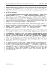
Bytes 123 – 126 contain write-only RAM for entry of a 32 bit password that allows
access to user writable EEPROM at locations 128-247. The default password for
Finisar devices is 0, however it can be set to any value at the factory to insure security
of the user writable EEPROM contents. Please contact your Finisar sales
representative for details on setting up a custom password. Once the password has
been entered into locations 123 – 126, a ‘1’ should be written to address 127 (readable
and writeable RAM cell). Note that the power-on default value of byte 127 is ‘0’. Once
these two steps have been completed, EEPROM at locations 128 – 247 is readable and
writable. The EEPROM remains readable and writable until either the password is
changed or byte 127 is set to 0.
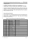
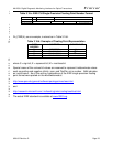
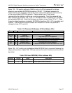
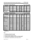
Table 3.19: Password Addresses (2-Wire Address A2h)
Byte Bit Name Description
120-122 All Reserved Reserved
123 All Password Byte 3 High order byte of 32 bit password
124 All Password Byte 2 Second highest order byte of 32 bit password
125 All Password Byte 1 Second lowest byte of 32 bit password
126 All Password Byte 0 Low order byte of 32 bit password
127 All User EEPROM Select ‘1’ selects user writable EEPROM at locations 128 - 247
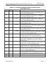
Bytes 128 – 247 contain user readable/writable EEPROM that is accessed following the
steps outlined above. Bytes 248 – 255 are reserved for control functions and should not
be written.
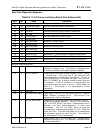
Table 3.20: User EEPROM (2-Wire Address A2h)
Address # Bytes Name Description
128-247 120 User EEPROM User-writable/readable EEPROM
248-255 8 Vendor Specific Vendor specific control functions