


AN-2030: Digital Diagnostic Monitoring Interface for Optical Transceivers F i n i s a r
9/26/02 Revision D Page 16
1
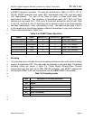
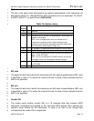
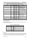
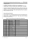
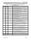
Table 3.10: I/O Timing for Soft Control & Status Functions 2
Parameter Symbol Min Max Units Conditions
TX_DISABLE assert time t_off 100 ms Time from TX_DISABLE bit set
1
until optical output falls below
10% of nominal
TX_DISABLE deassert time t_on 100 ms Time from TX_DISABLE bit
cleared
1
until optical output rises
above 90% of nominal
Time to initialize, including
reset of TX_FAULT
t_init 300 ms From power on or negation of
TX_FAULT using TX_DISABLE;
serial communication possible
TX_FAULT assert time t_fault 100 ms Time from fault to TX_FAULT bit
set.
LOS assert time t_loss_on 100 ms Time from LOS state to RX_LOS
bit set
LOS deassert time t_loss_off 100 ms Time from non-LOS state to
RX_LOS bit cleared
Rate select change time T_rate_sel
100 ms Time from change of state of Rate
Select bit
1
until receiver
bandwidth is in conformance with
appropriate specification
Serial ID clock rate f_serial_cl
ock
100 kHz n/a
Analog parameter data ready t_data 1000 ms From power on to data ready, bit
0 of byte 110 set
1
measured from falling clock edge after stop bit of write transaction.
3
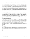
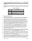
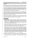
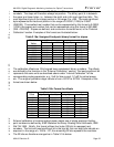
SFF-8472 Compliance 4
Byte 94 contains an unsigned integer that indicates which feature set(s) are 5
implemented in the transceiver. 6
7
Table 3.11: SFF-8472 Compliance 8
Data Address Value Interpretation
94 0
Digital diagnostic functionality not included or
undefined.
94 1
Includes functionality described in Rev 9.3
SFF-8472.
94 2 TBD
94 3 TBD
9
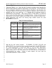
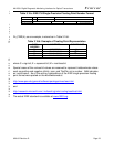
CC_EXT 10
The check code is a one byte code that can be used to verify that the first 32 bytes of 11
extended serial information in the SFP is valid. The check code shall be the low order 8 12
bits of the sum of the contents of all the bytes from byte 64 to byte 94, inclusive. 13