


EMULEX MODEL 355 SAN STORAGE SWITCH
USER’S GUIDE CHAPTER 2: SWITCH INSTALLATION
EMULEX CORPORATION 4
P
ART NUMBER 00041407-002 REV. B
SWITCH INSTALLATION
The switch can be installed in a rack or placed on a desktop.
Rack Installation
Installing the switch in an equipment rack requires an optional rack mount kit (sold separately). The rack
mount kit holds two switches. Contact a sales representative for more information or assistance in
purchasing a kit.
Installing the switch(es) in a rack requires the following items:
• Rack mount kit (Part Number 00651359-701)
• 4 thread forming screws, 6-32 x 1/4 100
° (included in the Rack Mount Kit)
• No. 2 Phillips screwdriver
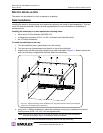
To install the switch(es) in the tray:
1. Turn the switch(es) over (upside-down) on a flat surface.
2. Turn the tray over (upside-down) and place it on top of the switch(es).
3. Align the tray and the switch(es) using the four holes indicated in Figure 2-1. Make sure that the
back lip of the tray is aligned with the back side of the switch(es).
4. Using a No. 2 Phillips screwdriver, attach the switch(es) to the tray by installing the 4 thread
forming screws (6-32 x 1/4 100
° ) into the aligned holes.
5. Turn the tray over with the attached switch(es) now on the top of the tray.
Note: While there are eight holes on each side of the tray, only the four holes indicated on
each side of the tray in Figure 2-1 should be used for the switch.
Figure 2-1: Diagram Depicting Switch Installation into Tray (Note: Switches and tray are displayed
upside-down to facilitate proper installation.)