


22618-17-0308Page 8
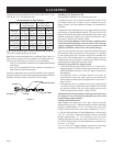
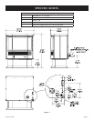
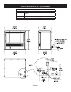
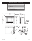
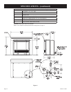
Model PV28SV50
Input BTU/HR (KW/H) 19,000 Rear - 9,000 Front
Height 25 1/8”
Width
28 3/16”
Depth 17 5/8”
Gas Inlet (Pipe) 3/8” Flair
Electrical - Unit has a 5’ (1.5 m) 3 pronged cordset for con-
nection to an approved 115 VAC 60 Hz maximum
AMPs - 5A wall receptacle.
Accessories
Part Number Description
PV-2H Top Cover - Slim Assembly
PV-4H Top Cover - Short Assembly
PVPK Pedestal Kit
PVE-1 6” Surround Assembly
PVSH Rear Shroud
TRW Wall Thermostat - Wireless Remote
FRBTC Battery Operated Remote w/Thermostat
FRBTP Battery Operated Remote w/Programmable Ther-
mostat
TMV2 Two-Stage Thermostats
CIPFP-1 Floor Pad Kit
CIFPB-1C Corner Floor Pad Kit
PVVK24H Direct Vent 24” Vent Kit
PVVK48H Direct Vent 48” Vent Kit
PVVK-SH Single Flue Horizontal Vent Kit
PVVK-SV Single Flue Vertical Vent Kit
PVVK-CFA Flex Vent Kit
PVCT Colinear Transition
PVVTC Vertical Termination Cap - 1.5”
PVCA Colinear Adapter
SPECIFICATIONS
INSTALLATION INSTRUCTIONS - GENERAL SAFETY INFORMATION
1. This installation must conform with local codes or, in the ab-
sence of local codes with NFPA54.
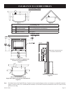
2. Provide adequate clearances around the product for servic
-
ing and ensure there are no obstructions to the combustion
air intake situated at the back of the heater. Refer to Page 15,
Figures 7 through 10.
3. The appliance must be installed on a flat, solid
continuous
surface (i.e. wood, metal, concrete). Please Note: Rough or
uneven surfaces can cause vibration or humming in the heat-
er.
4. The Mantis Power-Vent High-Effeciency Fireplace can be in
-
stalled in a wide variety of ways and will fit nearly any room
layout. It may be installed in a recessed position, framed out
into the room, or across a corner. For installation options re-
fer to page 15.
5. This appliance (Insert and Freestanding Models) needs to be
installed in such a way that the heater can be
removed at all
times to service the heater exchanger and flue fan located in
the rear section of the heater.
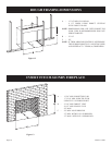
Note: Under no circumstances should the appliance be in
-
stalled under conditions which would not allow for
easy removal of the appliance to carry out routine
inspection and service to the appliance, to do so will
void the warranty.
Note: On Single Wall flue pipe installations (imitation zero
clearance fireplace) a minimum of 2” (50.8 cm) clear-
ance must be provided at the rear of the heater to enable
the heater to get sufficient combustion air to the air inlet
located at the rear of heater. Refer to installation instruc-
tions on page 15, Figures 7 through 10.
Note: Where a mantel surround is being used on insert installa-
tions and zero clearance fireplace installations, the com-
bustion air intake slot located in the top mantel surround
must have no obstructions to allow combustion air to en-
ter through the slot to the combustion air inlet located at
the back of the heater.