


22618-17-0308Page 24
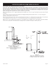
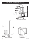
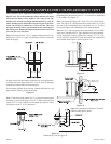
HORIZONTAL EXAMPLES FOR COLINEAR DIRECT VENT
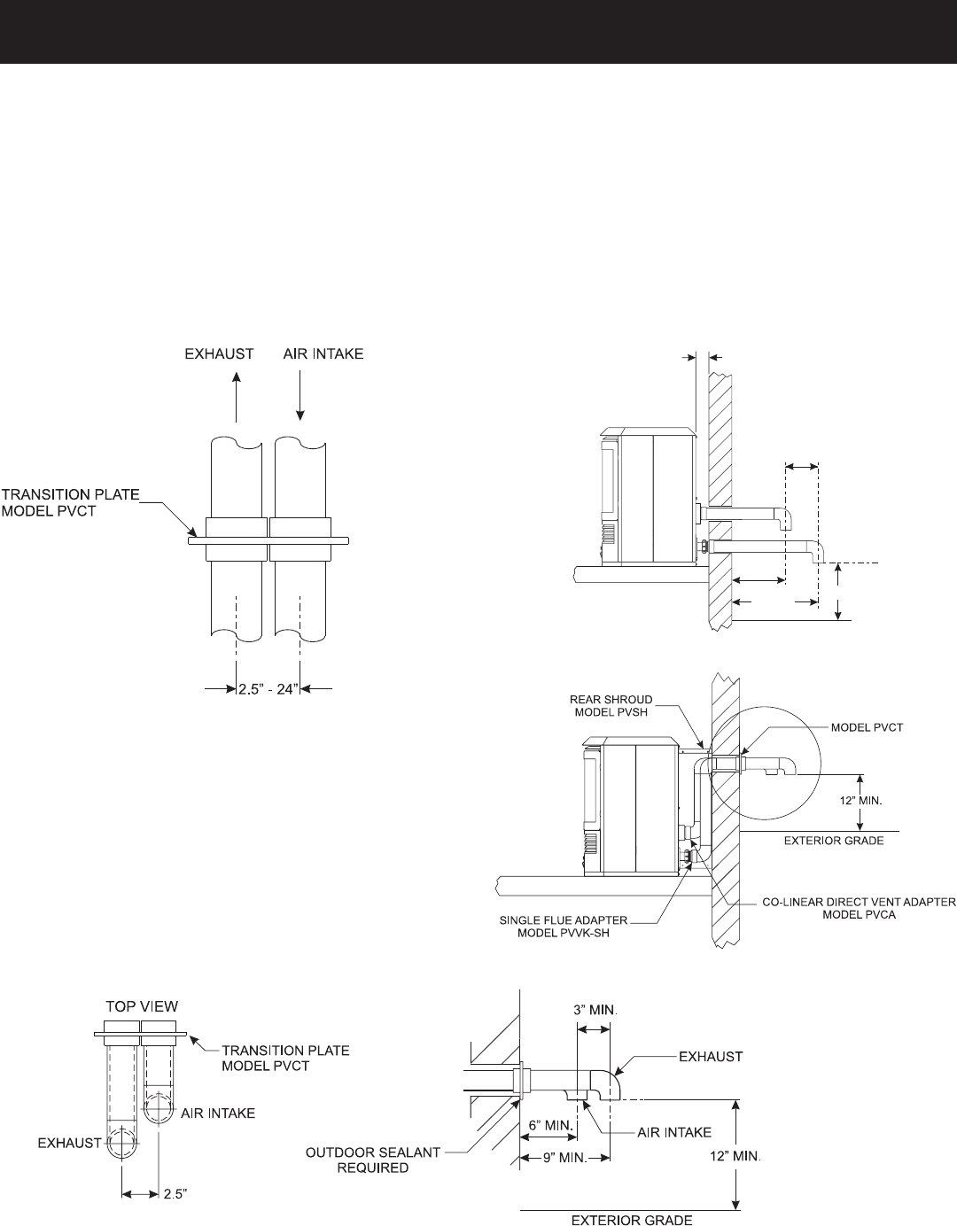
Figure 27
Enhanced top view of Figure 26
Figure 26
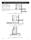
Max Vent Run - 40 ft. Equivalent With Three (3) 90° Elbows
Special Note: The vent terminal 90° elbow and first 90° elbow
off back of the heater, when within 6” (15.2 cm), do not con
-
tribute to the overall vent length measurement. For each 45°
elbow installed in the horizontal run, the length of the hori-
zontal run MUST be reduced by 1.5 feet (45 cm). This does
not apply if the 45° elbows are installed on the vertical part of
the vent system. Reduce the length of the horizontal run 3 feet
(91.4 cm) for every 90° elbow.
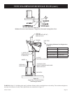
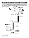
Note: On horizontal runs, a P.V.C. support clamp needs to be in-
stalled every 3 feet. No “sags” in horizontal vent runs; water will
settle in the pipe.
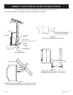
When installing a colinear horizontal, the minimum vent length
protruding from the outside wall is 6” (15.2 cm) for air intake and
9” for exhaust. See Figure 27.
Note: Horizontal discharge 90° elbow must be pointed down-
ward. See Figure 26. All horizontal runs require either a 1/4” per
foot rise to run condensation back to the heater, or a 1/4” per foot
downward slope to run condensation away from the heater.
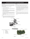
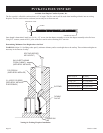
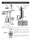
Note: All PVC vent run piping can be purchased at a local hard-
ware store. Schedule 40 PVC pipe should be used and cemented.
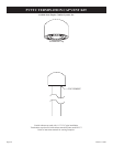
PVCA Horizontal Colinear Direct Vent Adaptor, PVVTC Cap,
PVVK-CFA Flex Kit and PVVK-SH Horizontal Vent Adaptor Kit
are available from Empire Comfort Systems, Inc.
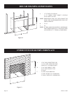
Figure 24
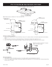
In both vertical and horizontal colinear direct vent applications,
a colinear transition plate model PVCT can be used to minimize
clearances between intake and exhaust pipes.
For horizontal colinear direct venting, exhaust and intake air, cap
pipes with 90º elbows, pointed downward.
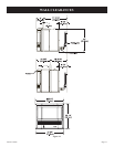
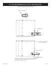
Note: If transition plate (model PVCT) is used, the measurement
for center to center of the pipes will be 2.5”. If the transition plate
(model PVCT) is not used, the measurement for center to center
of the pipes can be 3” to 24” maximum.
Note: Must maintain a minimum 3” between
exhaust outlet and air intake.
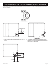
EXTERIOR GRADE
12” MIN.
9” MIN.
MIN.
2”
6” MIN.
3” MIN.
Figure 25