


22618-17-0308 Page 43
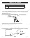
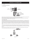
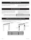
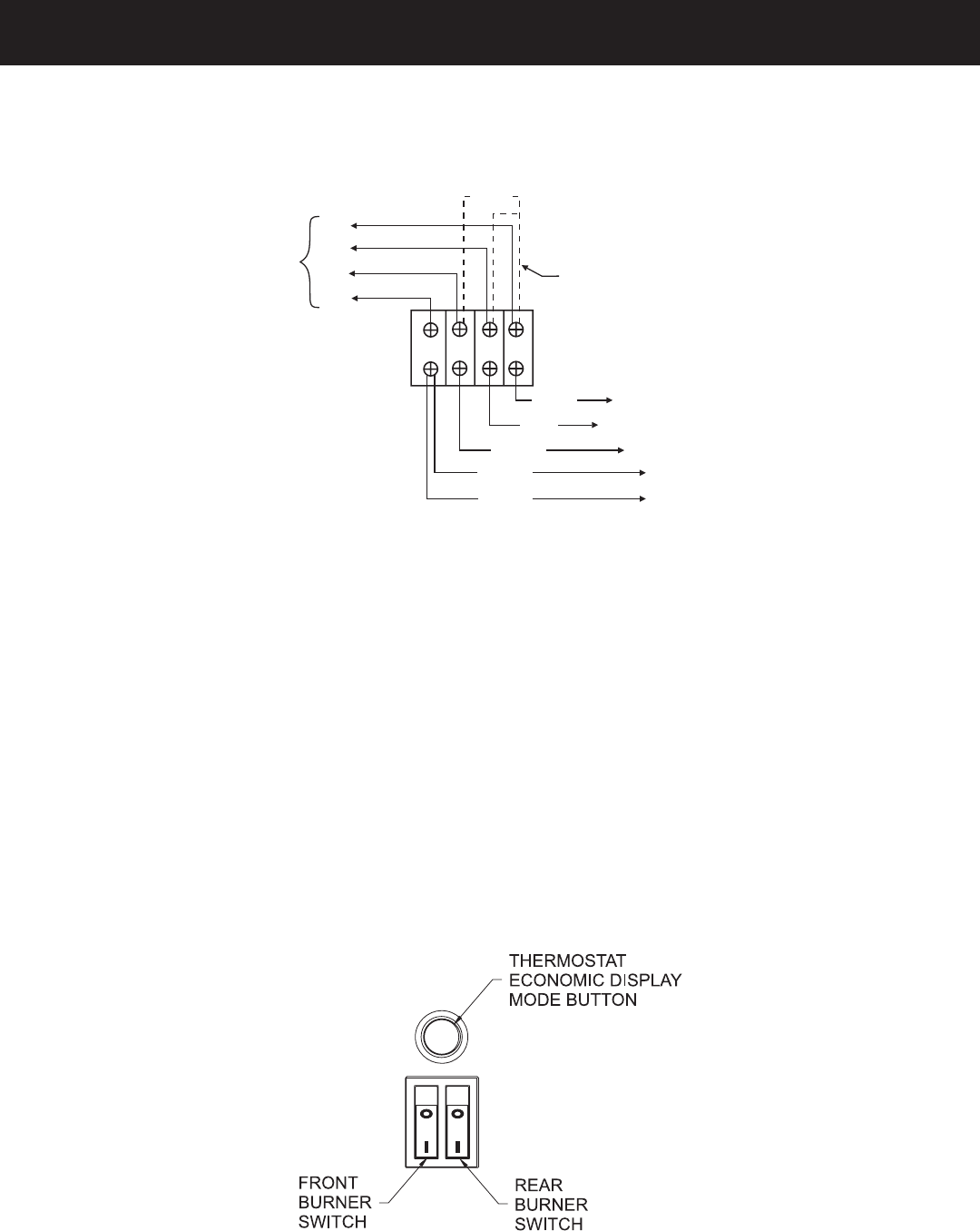
OPTIONAL CONTROLLERS
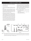
R: 24 Volt Hot
W
1
: Heat Relay Stage 1 (Front burner)
W
2
: Heat Relay Stage 2 (Rear burner)
C: 24 Volt Common
Figure 51
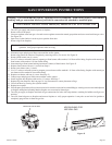
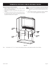
Replace front louver panel and plug unit into outlet. Turn both burner switches to ON position. Burner switches must remain in the ON
position for thermostat to function. Set thermostat using the instructions provided with the thermostat.
Note: When the heater or the Remote Control will not be used for long periods the burner switches should be in the OFF position,
also in summer the heater should be turned off at the power point.
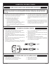
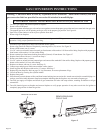
Economy Display Mode
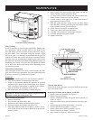
Economy Display Mode (Red Button Operation): The red button above the two burner switches (figure 52) is called the economy dis-
play mode and will only function when a Controller has been installed in the heater. The most common way to use this button is to set
the controller to Thermo mode with a desired temperature set for the heater to turn on and off, which is dependant on the ambient tem-
perature, location and the area the appliance is positioned. When using a controller both burner switches need to be in the ON position.
When the red button is pressed with both burner switches on, the front burner only will ignite or if already alight, it will now remain on
regardless of what function or temperature is set on the Remote Control. The red button acts as an override switch for the front burner
only.
In this situation only the back burner will turn on and off according to the setting on the Remote Control. By running the heater this way
you will use less gas and still have the aesthetic effect of the front burner. However, if the appliance is in a small area, this setting may
get to warm for you. To change the setting, press the red button so that it is not illuminated and the heater will revert back to its normal
operation.
Note: When the heater or the Remote Control will not be used for long periods the burner switches should be in the OFF position,
also in summer the heater should be turned off at the power point.
Figure 52
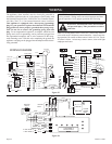
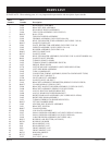
BLACK
WHITE
RED
TO
TRANSFORMER
BLUE
TO “T2” (REAR BURNER)
TO
“T1” (FRONT BURNER)
JUMPER WIRE
(TO BE REMOVED)
BLUE
W1 RW2C
BLUE
TO
“T1”
TO “T2”
C
TO
THERMOSTAT
W2
W1
R
JUNCTION
BLOCK