


22618-17-0308Page 44
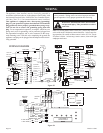
WIRING
(1) (2) BLACK
BLACK (3) (4) RED
YELLOW (5) (6) RED
BLUE (7) (8) BROWN
GREY (9) (10) RED
RED (11) (12) BLACK
BLACK (13) (14) RED
RED (15) (16) FRONT H.S.I.
FRONT H.S.I. (17) (18) REAR H.S.I.
REAR H.S.I. (19) (20) BROWN
WHITE (3-5-7) (1) BLUE
BLACK (8) (2) BLACK
(15) ORANGE
(13) RED
(11) BLACK
(9) BROWN
(7)
PURPLE
(5) BLUE
(3) WHITE
(1) YELLOW
GREEN/YELL
OW (16)
BLACK (14)
BLACK (12)
GREEN (10)
RED (8)
RED (6)
BLACK (4)
RED (2)
(5) YELL
OW
(3) BLACK
(1) GREY
ORANGE (6)
WHITE (4)
RED (2)
WATER LEVEL
SWITCH
TRANSFORMER
14 WAYRIBBON TO
FRONT PANELDISPLAY
FRONT BURNER
SWITCH
REAR BURNER
SWITCH
THERMISTOR
P1 TO
DISPLAY
P1 TO
DISPLAY
AIR PRESSURE
SWITCH
PIN 5
(NC)
(NO)
(COM)
TRANSFORMER
120V BLACK
PINS 4OR 6
CONV.FAN
PIN 13
GAS VALVE
80
C
VAL
VE /
INDP
FLUE FAN
PIN 3
PIN 6
PIN 4
120V WHITE
HSI
PIN 18
PIN 16
PIN 20
PIN 5
CONDENSATE
PUMP
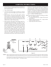
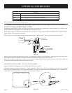
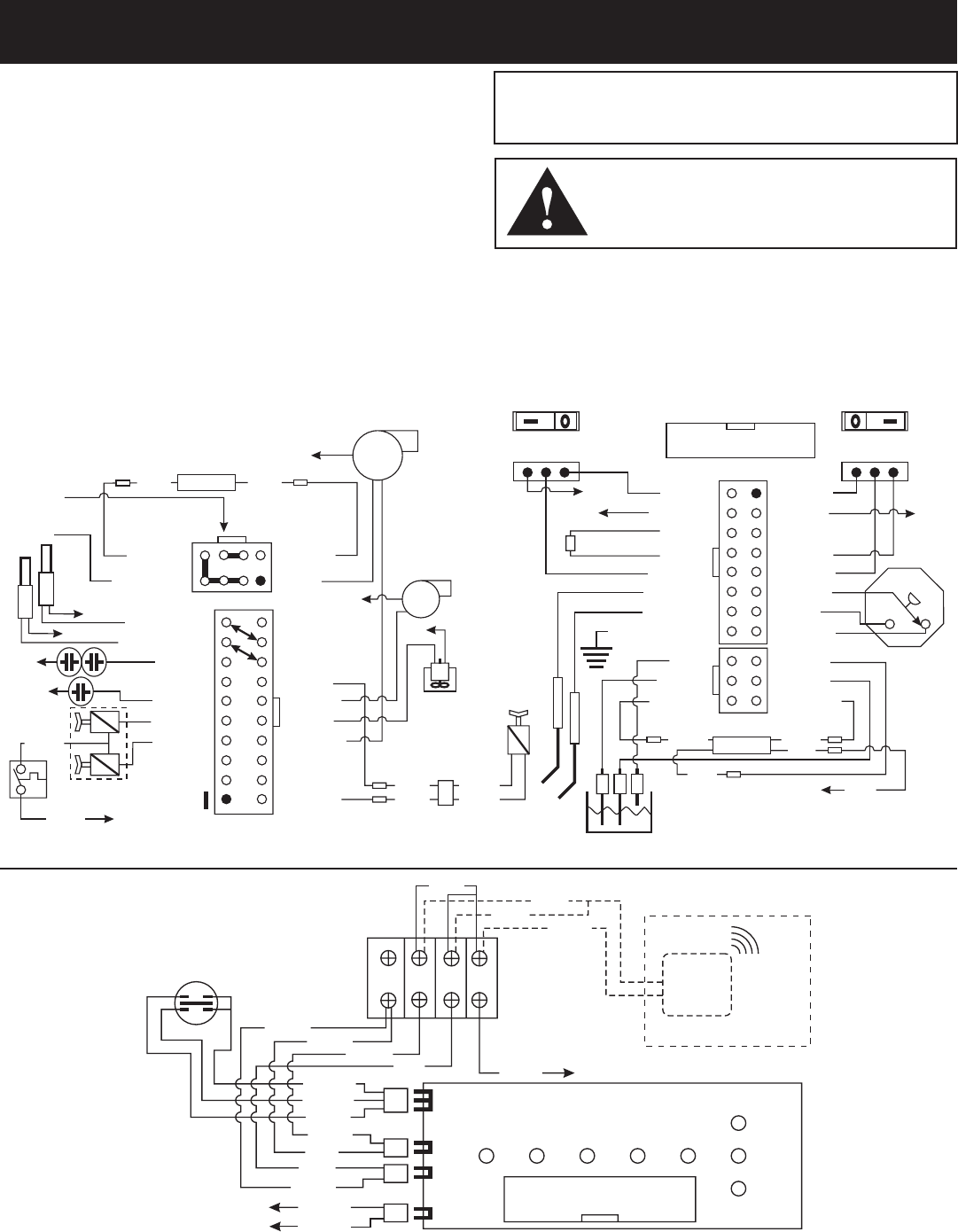
WIRING DIAGRAM
WHITE
BLACK
ORANGE
ORANGE
BLACK BLACK
ORANGE
YELL
OW
TRANSFORMER
TO JUNCTIONBLOCK
YELLOW
BLUE
BLUE
BROWN
BROWN
F
R
GREY
4 µF
3 µ
F
14 WAY RIBBON TO
CONTROL MODULE
P1
T1
T2
P2
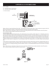
OPTIONAL
CONTROL
WIRING
RECEIVER
BLACK
WHITE
PURPLE
YELLOW
BLUE
WHITE
WHITE
BLACK
RED
R. BRN. THERM (4)
L. BRN. THERM (3)
BLACK
BLUE
WHITE
RED
BLUE
JUNCTION
BLOCK
TO
TRANSFORMER
BL
UE
INDICATOR
SWITCH
BLACK
WHITE
WHITE
+ -
W1
W2
C
R
The appliance, when installed, must be electrically grounded in
accordance with local codes or, in the absence of local codes, with
the National Electrical Code, ANSI/NFPA 70 or Canadian Electri-
cal Code, CSA C22.1, if an external electrical source is utilized.
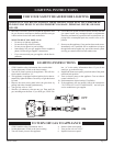
This appliance is equipped with a three-prong [grounding]
plug for your protection against shock hazard and should be
plugged directly into a properly grounded three-prong recep-
tacle. Do not cut or remove the grounding prong from this
plug. For an ungrounded receptacle, an adapter, which has two
prongs and a wire for grounding, can be purchased, plugged into
the ungrounded receptacle and its wire connected to the recep-
tacle mounting screw. With this wire completing the ground, the
appliance cord plug can be plugged into the adapter and be electri-
cally grounded.
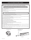
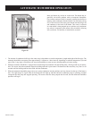
CAUTION: Label all wires prior to disconnection when ser-
vicing controls. Wiring errors can cause improper and dan-
gerous operation. Verify proper operation after servicing.
Note: For testing flame sensor circuit use a micro-amp meter in
series with sensor. Minimum current should be 1 micro-amp dur-
ing operation. Be careful as flame sensor is in the 115VAC circuit.
If current is below 1 micro-amp, remove sensor, clean with light
sandpaper and retest.
Figure 53
Figure 54
WARNING: Potential risk of fire, electric shock,
and personal injury. Take precautions to reduce
such risks.