


22618-17-0308Page 26
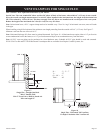
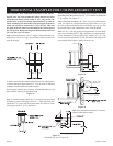
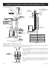
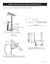
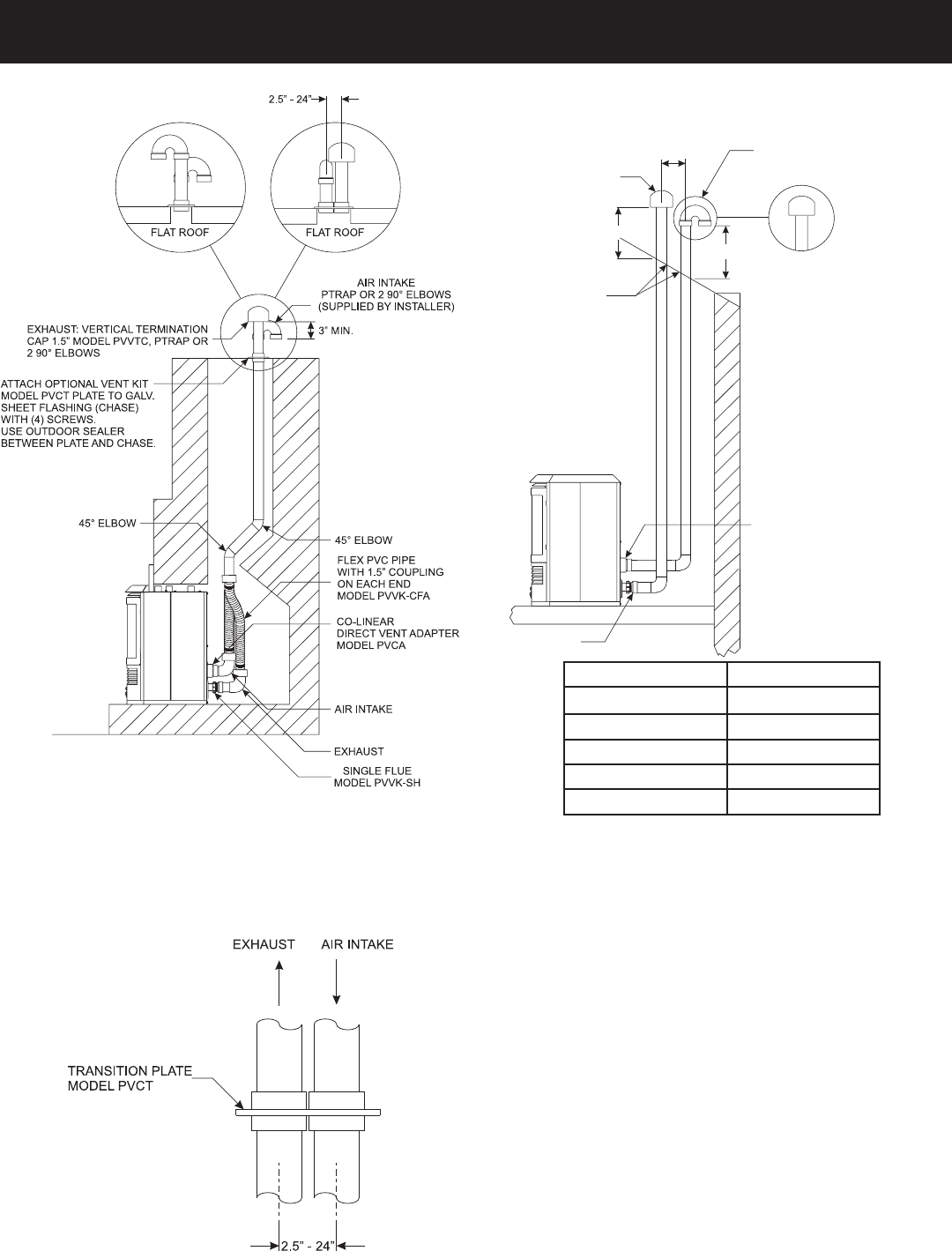
VERTICAL EXAMPLES FOR COLINEAR DIRECT VENT
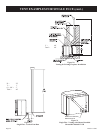
SINGLE FLUE
MODELPVVK-SH
CO-LINEAR
DIRECT VENTADAPTER
MODELPVCA
12
X
HEIGHT
FLASHING
REQUIRED
HEIGHT
AIR INTAKE
PTRAP, 2
90° ELBOWS (SUPPLIED
BY INSTALLER) OR TERMINATION CAP
MODELPVVTC. PTRAP TO
FACE
AWAY FROM ROOF
.
EXHAUST
TERMINATIONCAP
MODELPVVTC, PTRAP
OR
2 90° ELBOWS
OPTION
3” - 24”
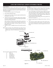
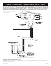
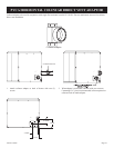
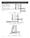
Colinear Direct Vent - Insert Installation
Figure 29
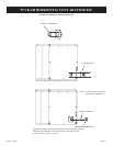
Colinear Direct Vent - Pitched Roof Installation
Figure 30
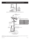
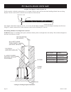
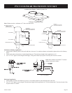
Determining Minimum Vent Height Above the Roof
WARNING: Major U.S. building codes specify minimum chimney and/or vent height above the rooftop. These minimum heights are
necessary in the interest of safety. These specifications are summarized in Figure 30.
ROOF PITCH H (Min.)
Flat to 6/12 12” (305 mm)
6/12 to 7/12 15” (381 mm)
Over 7/12 to 8/12 18” (457 mm)
Over 8/12 to 16/12 24” (610 mm)
Over 16/12 to 21/12 36” (914 mm)
Figure 31
In both vertical and horizontal colinear direct vent applications, a colinear
transition plate model PVCT can be used to minimize clearances between
intake and exhaust pipes.
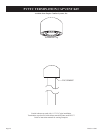
For exhaust and intake air, cap pipes with any of the following: Vertical
termination cap (model #PVVTC), PTrap, or two 90º elbows. When transi
-
tion plate (model PVCT) is used, two termination caps (model PVVTC) may
NOT be used.
Note: If transition plate (model PVCT) is used, the measurement for center
to center of the pipes will be 2.5”. If the transition plate (model PVCT) is
not used, the measurement for center to center of the pipes can be 3” to 24”
maximum.
Note: Exhaust must be a minimum
of 3” above air intake inlet.