


www.enviromaster.com
9
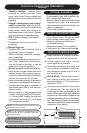
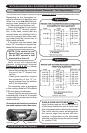
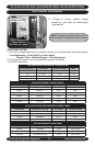
WLCA/WLHA High Wall Evaporator
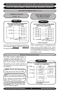
Figure 2 C
Figure 2 B
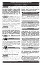
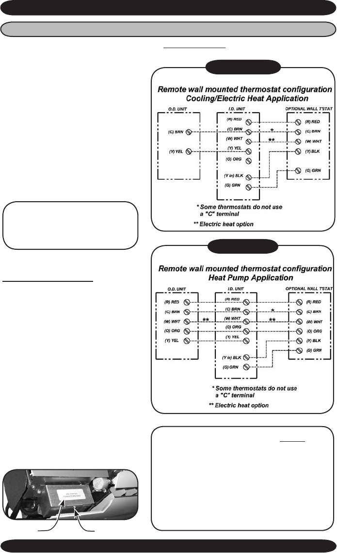
Heat Pump Connection Remote Thermostat – Two-Stage Heating
Low Volt interconnect diagram interconnect diagram Figures 2A, 2B & 2C for remote wall thermostat control.
SINGLE-ZONE HEAT PUMPS ONLY Two-
stage heating requires the combination of
a heat pump condenser and an indoor unit
that is equipped with an electric strip heater.
The indoor electric heater will energize as
the second stage heat source (the tem-
perature is dependent on the thermostat
selected) and also during the defrost mode
for models S1HA.
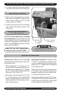
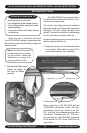
Depending on the thermostat re-
quired or selected, air handlers may
utilize four to six low
Volt intercon-
necting wires between the indoor
unit, thermostat and outdoor unit.
Some thermostats do not require
the use of the “C” (brown) connec-
tion. In this case, ensure that any
unused wires are insulated with a
wire nut to prevent them from mak-
ing contact with the junction box or
other metal surfaces.
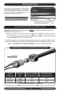
If the indoor unit has electric heat
then a “W” connection is required be-
tween the thermostat and indoor unit.
Refer to low Volt interconnect
diagram interconnect diagram
Figures 2A, 2B & 2C for remote
wall thermostat controls.
• Some thermostats do not require
the use of the “C” (brown) con-
nection.
• Heat pump operation requires
the connection of the “O” (or-
ange) terminal from the outdoor
unit to the thermostat.
The reversing valve is energized
in the cooling mode for EMI models
S1H heat pump condensers.
Ensure that any unused wires are
insulated with a wire nut to prevent
contact with the junction box or other
metal surfaces.
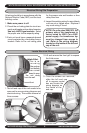
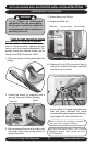
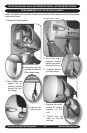
Once certain all electrical connetions
are made replace control box cover.
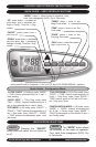
NOTE: If the control is con-
gured for unit mount con-
trol do NOT connect a wall
thermostat to the unit.
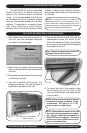
Control box
Replace screw
WLCA/WLHA HIGH WALL EVAPORATOR INSTALLATION INSTRUCTIONS