


www.enviromaster.com
7
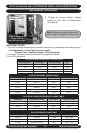
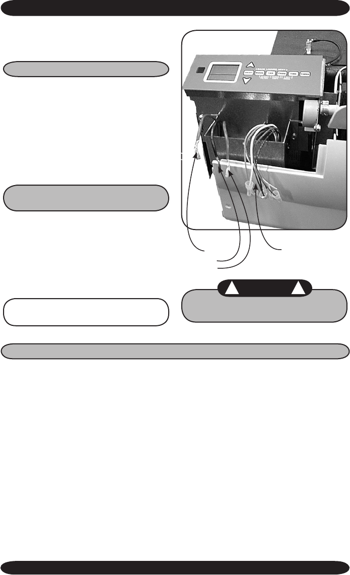
WLCA/WLHA High Wall Evaporator
Note: All low Volt interconnect
wiring must be at least 18 AWG.
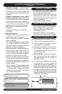
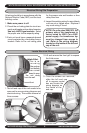
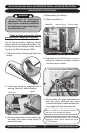
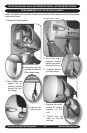
High Volt Electrical Wiring
5. Refer to the wiring diagram to connect
the power wire to Black L1 and the other
wire to Red or White (115V) L2 at the
power connector location.
6. Connect the ground wire to the ground
lug or lead at the same location in the
control box.
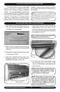
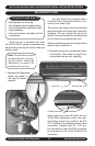
4. To access High and Low wiring remove
the screw on the front of the control box.
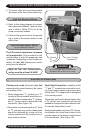
Low Volt Interconnect Wiring
For Unit Mounted Controls
The 24V control transformer is located
in the evaporator. This provides low Volt
control power to both the evaporator and
condenser. Depending on the models se-
lected, the low Volt interconnect control
wiring may be effected.
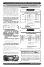
Cooling only units utilize two low
Volt
interconnecting wires between the indoor
and outdoor units.
• Wires designated “Y” (yellow) and “C”
(brown) of the air handler should be con-
nected to the corresponding “Y” (yellow)
and “C” (brown) wires or terminals of the
condenser. (See Figure 1A)
• Other wires or terminals such as “R” (red)
or “O” (orange) may not be needed and
should be protected by a wire nut from
making contact with the junction box or
other metal surfaces.
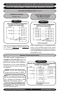
Heat Pump Connection: In addition to the
“Y” and “C” connections required for cool-
ing, heat pumps require a reversing valve
control wire “O” (orange) that is energized
in the cooling mode.
If the indoor unit has an electric heater, then
a ”W” (white) wire connection will also be
needed to energize the indoor electric heat.
If a remote thermostat is used.
Heat pumps models require an “R” connec-
tion between the indoor and outdoor unit to
provide power to the defrost control board
in the condenser. (See Figure 1B)
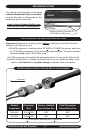
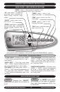
Units With Or Without Heat
Low Voltage
Connections
Ground
L1
L2
Be sure to keep any un-used wires
insulated with a wire nut or crimp.
WLCA/WLHA HIGH WALL EVAPORATOR INSTALLATION INSTRUCTIONS
! !
WARNING