


www.enviromaster.com
31
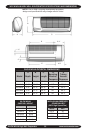
WLCA/WLHA High Wall Evaporator
TROUBLESHOOTING PROCEDURE Continued
While in test mode, all timers are
eliminated. Avoid short cycling the
compressor. After system checks
are complete, the control must be re-
turned to normal operation. DO NOT
LEAVE THE SYSTEM IN TEST
MODE!
LOW VOLT CONTROLS
Cooling Only Units
Cooling only units utilize low Volt
interconnecting wires between the indoor
unit, outdoor units and thermostat. For air
handlers with unit mounted controls, wires
(WLCA/WLHA) designated “Y” (yellow) and
“C” (brown) of the indoor air handler should
be connected to the corresponding “Y”
(yellow) and “C” (brown) wires or terminals
of the outdoor condenser. Other wires or
terminals such as “R”(red) or “O” (orange)
may not be needed and should be protect
by a wire nut from making contact with the
junction box or other metal surfaces.
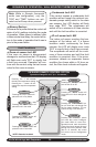
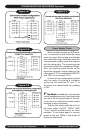
Refer to low Volt interconnect diagram
interconnect diagram Figure 1 for unit
mounted controls and Figure 2 for remote
thermostat connection.
A 24V transformer located in the indoor
air handler unit provides low Volt control
power to both the indoor air handler and
outdoor condenser. The 24V power supply
can be measured by placing a meter across
the “R” and “C” low Volt terminals of the
air handler. The air handler will switch on
and off the condenser through the yellow
(Y) wire. When the air handler is calling for
cooling, 24V can be measured between
terminals (wires) Y and C.
Electric Heat
Units with electric heat utilize a control
relay located on the circuit board in the
control box. As a safety feature, an auto
resetting limit switch located on the heater
end plate or on the heater assembly will
interrupt power to the heater should an
over-heat condition occur. Each electric
heat assembly is also equipped with a one
time fuse link (if trigered a new fuse link is
required). Should electric heat temperatures
rise above the auto resetting limit switch, a
non-resetting, one time fuse link will open
and the heater will remain off.
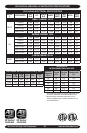
The following current values apply
when the unit is connected to a 230V power
supply. These values include fan motor cur-
rent. If the supply power is different, this will
in turn affect the amp draw of the heater.
5k
W = 22.3 amps, 4kW = 18 amps,
3k
W = 13.5 amps.
Optional Heat Pump
with Electric Heat
Heat pump units with electric heat utilize
four to six interconnecting, low Volt wires
depending control setup and/or thermostat
selected. Refer to the low
Volt interconnect
section and
Figures 1 & 2 for your particular
unit.
A 24V transformer located in the indoor
air handler provides low
Volt control power
to both the air handler and condenser. With
high
Volt power supplied to the condenser,
24
V can be measured across the red (R)
and brown (C) wires at all times.
Cooling: The air handler will cycle
the condenser on and off through the
yellow (Y) wire. To check for a condenser
signal, select cooling mode on the indoor
unit or thermostat and place the set-point
temperature below room temperature.
Then, with a voltmeter check for 24
Volts
across the yellow (Y) and brown (C) wires.
If no signal is found then re-check all wiring
connections to ensure that they match the
low Volt interconnect diagram. Check the
output of the 24V transformer (located in
the air handler) to ensure that the control
voltage is present.
! !
CAUTION