


Digital Monitoring Products SCS-1R Installation Guide
14
InstallatIon
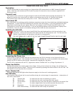
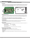
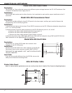
Model SCS-208 Power Cable
Description
The SCS-208 is a 2-foot cable that connects the different system voltages between the SCS-130 Transformer Card
J3 and SCS-120 Multibus Power Supply Card J3.
Installation
The SCS-208 cable can be used in either direction, but is polarized on each end for proper installation to the J3
connectors.
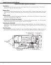
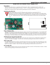
Model SCS-203 Convenience Panel
Description
The SCS-203 provides cabling for three RS-232 ports for the host output, auxiliary port (used for Remote Link
programming), and an activity log printer.
Installation
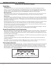
1) Install the metal plate with the three 25-pin RS-232 connectors on the SCS-1R Receiver backplate using the two
6-32 x 1/4” screws provided.
2) Install the three 10-pin at cable connectors to the SCS-150 Receiver ports A1, A2, and A3.
a) Connect the ribbon cable marked A1(Activity Log) to port A1.
b) Connect the ribbon cable marked A2(Aux) to port A2.
c) Connect the ribbon cable marked A3 (Host Output) to port A3.
3) Connect the printer using a DMP Model 389 Printer Cable and host computer using a DMP model SCS-204 Host
Cable (see below) to the appropriate RS-232 connectors.
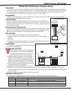
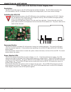
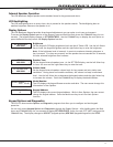
Model SCS-204 Host Cable
Description
The SCS-204 is a 10-foot RS-232 cable that connects a host
computer to the SCS-1R Receiver.
Installation
Connect the SCS-204 cable from a host computer to the SCS-203
Convenience Panel center connector marked “HOST OUTPUT”.
THE END OF THE CABLE MARKED “HOST” MUST BE INSTALLED ONTO
THE HOST COMPUTER.
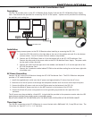
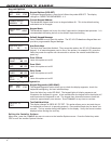
Host Cable
If you are using a cable different from the SCS-204, be sure the
cable pin out matches the drawing below.
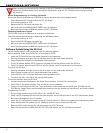
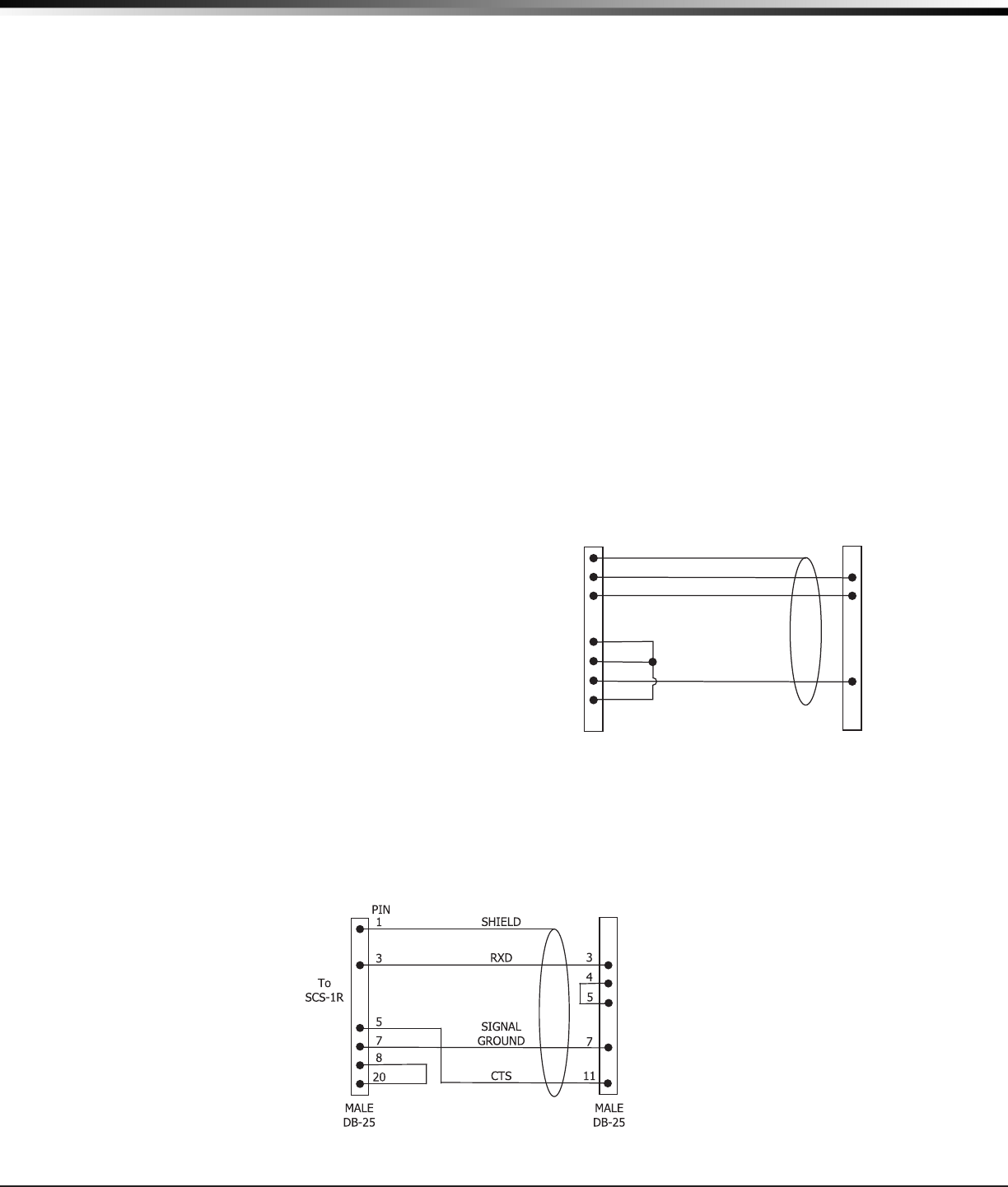
SCS-1R Printer Cable
Printer Cable Pinout
Note: UL central station applications must use a serial printer that is listed for Fire Protective Signaling Systems.
To Okidata
Printer
PIN
SHIELD
1
2 RXD
3 TXD
4
5
7
8
SIGNAL GROUND
MALE
DB-25
DB-25
(DB-9)
2 (3)
3 (2)
7 (5)
Connect to
HOST
COMPUTE
R
(DTE)