


SCS-1R Installation Guide Digital Monitoring Products
7
InstallatIon
Model SCS-150 Receiver Processor Board
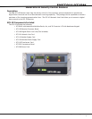
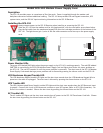
Description
The SCS-150 is the main system processor for the SCS-1R Security Control Receiver and controls the line cards, the
LCD display, the printer (if used), and data output to a host automation system. The SCS-150 contains the software
for system operation, the line conguration, and all time keeping functions. Programming can be done from the
front panel of the SCS-1R Receiver or via Remote Link version 1.47 or higher.
Compatibility
The SCS-150 is compatible with the SCS-100 Dialer Line Cards and the SCS-101 Network Line Card using Level E
hardware with Version 200 or higher software
.
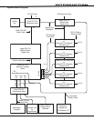
Line Card Slots
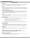
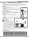
The SCS-150 Receiver Processor Board has a port (J6) for a line card connector
and has ve cables to support single dialer or ethernet cards. Slide the Line Card
Cable Connector onto the J6 port on the SCS-150. Connect the line card cables to
the existing line cards.
Communication Output Ports
The SCS-150 receiver has three ports to use for peripheral communication. The A1
port is used for printing to the Activity Log, the A2 port is for programming using
Remote Link, and the A3 port is used as a host automation output port.
SCS-150 LEDs
1) Far Left LED: Flashes constantly. This is the heartbeat LED.
2) Center Left LED: On when the SCS-1R is saving data, such as programming
changes.
3) Not used.
4) Far Right LED: On if memory resources are ever too low, such as thousands of
messages pending at the LCD display or the printer.
Reset Button
The reset button resets the SCS-150 receiver but does
not clear the stored events.
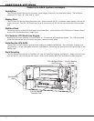
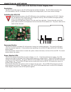
Installing the SCS-150
Always remove power to the SCS-1R Receiver
when installing or removing any components.
1)
Check that the S2 dip switch settings on the
SCS-150 are set to OFF for Normal Operation.
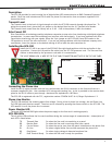
2) Slide the center connector of the new keypad
cable onto the keypad PCB. Connect the end
labeled “J15” to the SCS-150 Keypad J15 header.
Connect the other end to the SCS-110 Modem
Power Supply card with Brown stripe to the top.
3)
Slide the SCS-150 into the SCS-RACK lowest position,
component side up. Press into place.
4)
Install the SCS-203 cables labeled “A1” to port A1, “A2” to port A2, and “A3” to port A3 (Brown stripe to the right).
5)
Slide the Line Card Cable Connector onto the J6 port on the SCS-150 (Brown stripe to the right).
Connect the
line card cables to the existing line cards making sure that the brown wire always faces up and the cable labled
1 is to the right.
6) Once all connections are completed, power up the SCS-1R.
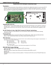
Dip Switch Settings (S2)
Dip switches 1-4, designated as S2 on the SCS-150 board, have the following settings and usage:
Settings: 0 is OFF, 1 is ON
1 2 3 4 Function Description
0 0 0 0 Normal Operation Used during normal receiver operation
1 0 1 0 Default Programming Set the receiver programming stored in EEPROM to factory defaults
1 1 0 1 Update Software Used for software updates with the SD card
1 1 1 1 Clear Events Clear all pending LCD display, printer, and host output events
Keypad
J15
A3 A2
A1
12
3
4
5Not Used
SCS-150
Line Card
Connector
J6
1
23
4
5
Model SCS-203
Convenience
Panel
A3
A2 A1
Dip Switches
1 2
3
4
ON
S2
LEDs
1 2
3
4
S1
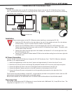
Reset
Connect to Keypad PCB
with light brown
stripes to the right
Connect to
SCS-110 with
light brown stripe
to the top
Connect
to the SCS-150
J15 header
Light Brown
Stripe
(Pin 1)
Black
Stripe
LCD Cable Detail