


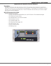

SCS-1R Installation Guide Digital Monitoring Products
13
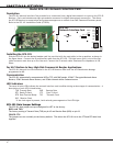
InstallatIon
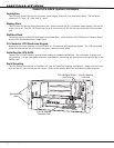
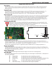
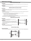
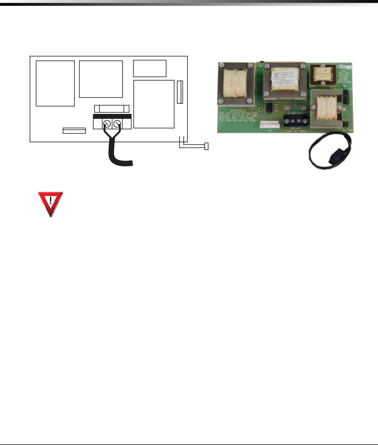
Model SCS-130 Transformer Card
Description
The SCS-130 provides power to the SCS-110 Modem Power Supply Card and the SCS-120 Multibus Power Supply
Card. Two terminals are provided for connecting 120 VAC to the system. A power cord is provided for connecting
the multibus rack cooling fan.
3 Amp 250V
To fan
COM
J3
J2
HOT
AC Power Cord
Installation
Always remove power to the SCS-1R Receiver when installing or removing the SCS-130.
1. Install the SCS-130 with J2 on the right side on the rear of the modem rack and J3 on the bottom
as shown above. Four 6-32 screws with lock washers are provided.
2. Connect the SCS-208 Power Cable to J3 on the bottom left of the SCS-130 Transformer Card.
Connect the other end of the power cable to the SCS-120 Multibus Power Supply. The power cable
can be used in either direction.
3. Connect the cable from the right end of the modem rack labeled J2 to J2 on the right side of the
SCS-130 Transformer Card.
4. Connect the 2-conductor cables labeled TO FAN to the multibus cooling fan on the lower right side
of multibus rack.
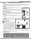
AC Power Connection
Connect 120 VAC to the SCS-1R Receiver through the SCS-130 Transformer Card. The SCS-1R Receiver backplate
provides a 7/8” conduit knockout.
1. Install the supplied strain relief onto the AC power cord approximately 12 inches from the AC wires.
2. Feed the end of the AC power cord through the backplate knockout until the strain relief snaps into place.
3. Connect the White AC power cord wire to the COM terminal on the bottom of the SCS-130.
4. Connect the Black AC power cord wire to the HOT terminal on the bottom of the SCS-130.
5. Connect the Green AC power cord ground wire to the grounding lug located on the right side of the
enclosure.
The AC power must be provided by a listed UPS. A signal shall be provided at the operators console when the UPS
power source switches from primary power to secondary power.
DO NOT APPLY POWER TO THE RECEIVER UNTIL THE REAR COVER IS REPLACED ON THE RECEIVER CABINET.
Three Amp Fuse
The 120 VAC connection to the SCS-1R Receiver is current limited with a DMP Model 319, 3 Amp 250 volt fuse. The
3 Amp fuse is a Type AGC 1/4” x 1 1/4” fast blow.