


Digital Monitoring Products SCS-1R Installation Guide
6
InstallatIon
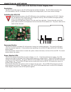
Model SCS-RACK System Enclosure
Description
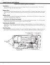
The SCS-RACK houses the receiver processor, power supply, line cards, and associated cables. The enclosure
measures 8.75” high, 19” wide, and 12” deep.
Modem Rack
The SCS-RACK top portion holds the modem rack, which connects the SCS-110 Modem Power Supply Card and up
to ve line cards. The SCS-130 Transformer Card for connecting the 120 VAC mounts on the rear of the modem
rack.
Multibus Rack
The bottom portion of the SCS-RACK holds the Multibus Rack, which holds the SCS-150 Receiver Processor Board
and the SCS-120 Multibus Power Supply Card.
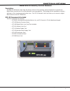
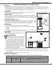
32-Character LCD Membrane Keypad
Mounted on the front faceplate of the SCS-RACK is a 32-character LCD Membrane Keypad. The LCD and keypad
come pre-mounted and pre-wired with the power cable and ribbon cable.
Installing the SCS-RACK
Connect the SCS-RACK to earth ground before making any module connections. Use a minimum 14 gauge wire
for grounding. A crimp type spade connector is provided for connecting the ground wire to the ground lug on the
modem rack.
Rack Mounting
The SCS-1R must be mounted in a standard 19” rack for listed Fire Signaling applications. Simply slide the entire
unit into the 19” rack and secure with screws. Refer to the drawing below for rack-mounting hole locations.
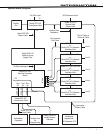
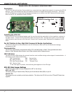
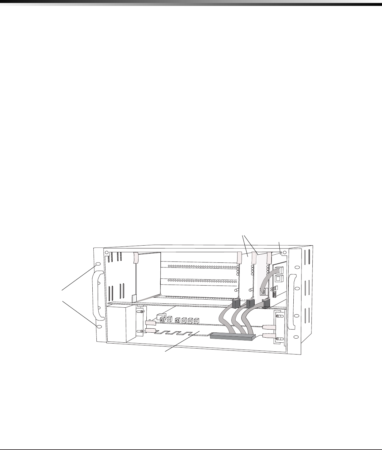
SCS-100 Digital Dialer
Line Cards
Line Card Connector
SCS-150 Receiver
Processor Card
Rack-Mounting
holes
SCS-101 Network
Line Card