


Digital Monitoring Products SCS-1R Installation Guide
10
InstallatIon
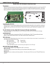
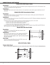
Model SCS-101 Network Interface Card
Description
The SCS-101 Network Interface Card provides for a connection from a digital data network to a port on the SCS-1R
Receiver. Each card includes one eight-pin modular connector for digital data network connection. This allows
the SCS-1R Receiver to accept alarm and system messages over a network from DMP Command Processor panels.
Refer to the SCS-101 Installation Guide (LT-0320).
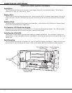
SCS-101
Network Interface Card
TXD
RXD
RTS
CTS
DTR
TXC
RXC
Serial Input
Red Black
J8
TXD RXD
2
3
3
2
J3 J4J2
CLK
DCO
J5
FORCE
CTS
8-Pin Modular
Plug
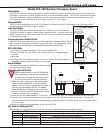
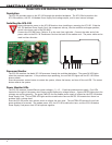
Installing the SCS-101
Slide the SCS-101 into the desired modem rack line card slot with the card puller in the up position, as shown in
the gure above. Connect the 10-position at cable from the SCS-150. The light brown (pin 1) wire of the at
cable connector must face up on the line card. Connect the IP network cable. Maximum line impedance is 100
Ohms.
For ULC Medium to Very High Risk Commercial Burglar Applications
The SCS-101 Network Line Card installed in the SCS-1R Receiver must have the ACK Substitution Message
programmed as NO.
Communication
The SCS-101 automatically communicates UDP or TCP with DMP panels, iCOM-E™ Encrypted Network Alarm
Routers, iCOM™ Network Alarm Routers, and iCOMSL Network Alarm Communicators.
LED Indicators
The seven bi-color LEDs indicate the network interface card condition during various stages of communication. A
description of each LED is listed below:
TXD Transmit Data RXD Receive Data
RTS Ready To Send CTS Clear To Send
DTR Data Terminal Ready TXC *Transmit Clock
RXC *Receive Clock
* If the clock signal is present, both red and green segments of the LEDs light.
SCS-101 Data Jumper Settings
The SCS-101 data jumpers are pre-congured for NET at the factory.
RXD and TXD
The factory setting is Transmit Data (TXD) on pin #2 and Receive Data (RXD) on pin #3.
FORCE CTS
The jumpers are set vertically as the factory default. This allows the SCS-101 to tie the CTS and RTS data lines
together.