


www.desatech.com 113110-01A
20
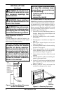
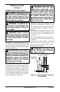
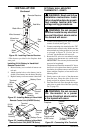
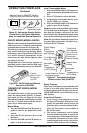
Figure 29 - Installing Remote Receiver
* Wire harness provided in the fireplace hard-
ware pack.
Wires from
Valve
Wire Harness*
Black
Wire
Red
Wire
Red Wire
Black Wire
Remote Receiver
INSTALLATION
Continued
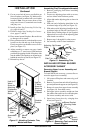
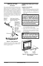
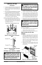
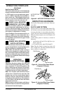
Installing 9-Volt Battery in Hand-Held
Remote Control Unit
1. Remove battery cover on back of remote con-
trol unit.
2. Attach terminal wires to the battery (not in-
cluded). Place battery into the battery housing.
3. Replace battery cover onto remote control unit.
Figure 30 - Installing Battery in Hand-Held
Remote Control Unit (GHRCB Series)
Battery Cover
9-Volt
Battery
Terminal
Wires
Remote
Control
Unit
Battery
Housing
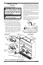
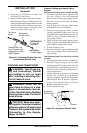
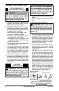
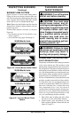
Figure 321- Installing Battery in Hand-Held
Remote Control Unit (GHRCTB Series)
Remote
Control
Unit
Battery Cover
Battery
Housing
9-Volt
Battery
Terminal
Wires
OPTIONAL WALL MOUNTED
THERMOSTAT - GWMT1
WARNING: Read and follow
installation instructions. Instal-
lation should be done by a quali-
fied installer familiar with low-
voltage wiring procedures.
WARNING: Do not connect
this thermostat to any electrical
source! Electrical shock and/or
fire hazard will occur.
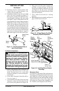
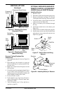
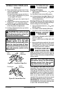
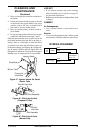
1. Connect one terminal of 25 ft. wire to bottom
contact of switch (see Figure 32).
2. Connect remaining wire terminal to the “TH”
terminal on the control valve. Make sure that
wire terminals are in the positions on your unit
as pictured in Figure 32. If wires are not
“crossed” the thermostat will not work.
3. Route the 25 ft. wire to a convenient location
to mount your thermostat (no outside wall).
IMPORTANT:
The wire may be shortened but
must not be lengthened.
The thermostat should be mounted 54" above
the floor in a location where there is good air
circulation. Avoid heat sources such as lamps,
direct sunlight, fireplace, or heat and air con-
ditioning ducts.
4. Gently remove the cover of the thermostat
from the base. Grasp the sides of the cover
firmly and pull to separate from the base.
5. Feed the electrical wires through the rectan-
gular slots on each side of the base (see Fig-
ure 33, page 22).
WARNING: Do not connect
the thermostat to a power
source. Electrical shock and/or
a fire hazard will occur.
Figure 32 - Connecting Wire Terminals
AU
TO
OFF
O
N
One terminal
of 25 ft. wire
Switch on Gas
Fireplace
To Wall Thermostat
or Switch
Control
Valve