


108954
14
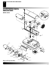
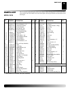
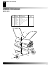
SERVICE PROCEDURES
Continued
CAUTION: Ignition control assembly contains
electrostatic components. Handle the assembly by
the edges of the printed circuit board. Do not touch
any of the quick connect terminals or electronic
components.
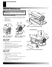
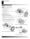
Installing the New Assembly
1. Align the five holes in the assembly with the five printed cir-
cuit board supports in the side cover.
2. Holding the assembly by the edges of the printed circuit board,
apply downward pressure until all five tabs on the printed cir-
cuit board supports springlock into place. Pull up on assembly
to verify this (see Figure 30).
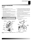
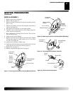
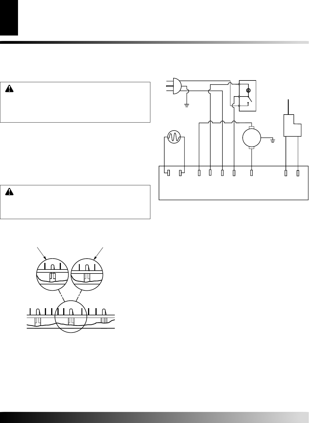
3. Connect the nine wire leads to the ignition control assembly as
shown in the wiring diagram in column 2.
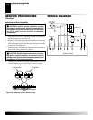
Figure 30 - Attaching Circuit Board to Tabs
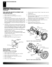
CAUTION: Double check connections. Connect-
ing ignition control assembly wrong could result in
damage to the ignition control assembly and/or other
components in the heater assembly.
Unacceptable Acceptable
Unacceptable
Acceptable
WIRING DIAGRAM
(7)
(2)(1)
(8)
(3) (4) (6)
(N)
(5)
1a
1
1b
Power Plug
240 V/50Hz
Ignition Control
Green-Yellow
Green-Yellow
Ignitor
Photocell
White
White
Red
Brown/White
Brown
Blue
Blue
Blue
Blue
ON/Off Switch
Black
Black
Motor
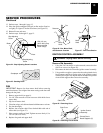
4. Using the 5/16" nut driver or socket wrench reinstall side cover
to heater. Tighten screws until snug. Do not over torque!
SERVICE PROCEDURES
WIRING DIAGRAM