


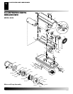
108954
12
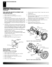
PUMP ROTOR
(Procedure if Rotor is Binding)
1. Remove upper shell (see page 8).
2. Remove filter end cover screws using 5/16" nut-driver.
3. Remove filter end cover and air filters.
4. Remove pump plate screws using 5/16" nut-driver.
5. Remove pump plate.
6. Remove rotor, insert, and blades.
SERVICE PROCEDURES
Continued
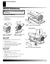
FUEL AND AIR LINE REPLACEMENT AND
PROPER ROUTING
1. Remove upper shell (see page 8).
2. Remove side cover screws using 5/16" nut driver.
3. Remove side cover.
4. Inspect fuel and air line hoses for cracks and/or holes. If fuel
line hose is damaged, disconnect from nozzle adapter (see Fig-
ure 17 or 18, page 11) and from fuel filter (see page 8). If air
line hose is damaged, disconnect from nozzle adapter (see Fig-
ure 17 or 18, page 11) and from barb fitting on pump end cover
(see Figure 21).
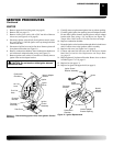
5. Install new air and/or fuel line. Attach one end of air line hose
to barb fitting on pump end cover (see Figure 21) and the other
end to nozzle adapter (see Figure 17 or 18, page 11). Attach
one end of fuel line hose to fuel filter (see page 8) and the
other end to nozzle adapter (see Figure 17 or 18, page 11).
For GK20 model heaters, route air and fuel lines approximately
as shown in Figure 17, page 11.
Note:
Hoses are not to be touching photocell bracket.
For GK30 model heater, route air and fuel lines approximately
as shown in Figure 18, page 11.
Note:
Hoses are not to be touching photocell bracket.
6. Replace side cover.
7. Replace upper shell and fan guard (see page 8).
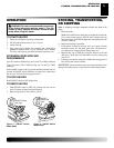
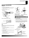
Figure 21 - Air Hose to Barb FItting
Barb Fitting
Air Hose
Pump End
Cover
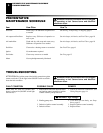
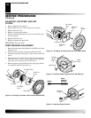
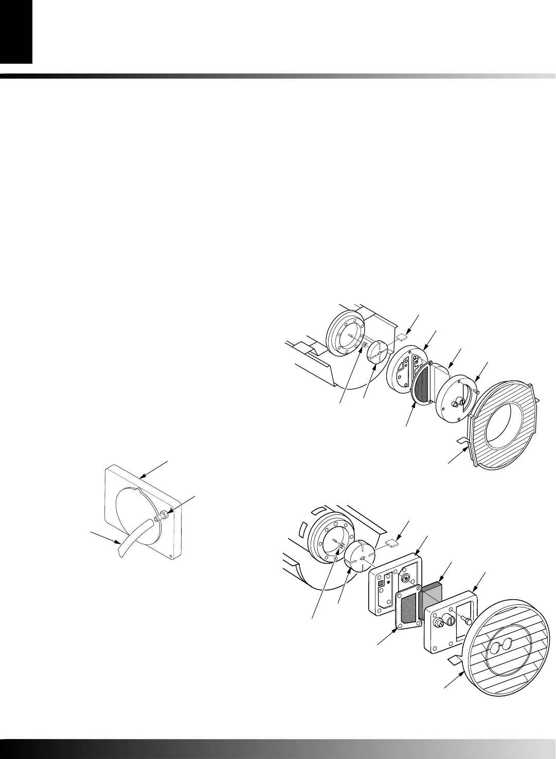
Figure 22 - Rotor Location, Model GK20
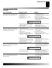
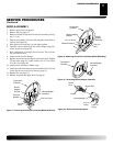
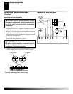
Figure 23 - Rotor Location, Model GK30
Insert
Blade
Rotor
Pump Plate
Air Intake Filter
Air Output
Filter
Pump Plate
Insert
Rotor
Blade
Filter End Cover
Air Intake Filter
Air Output
Filter
Fan Guard
Fan Guard
Filter End Cover
7. Check for debris in pump. If debris is found, blow out with
compressed air.
8. Install insert and rotor.
9. Check gap on rotor. Adjust to .076/.101 mm (.003"/.004") if
needed (see Figure 24, page 13).
Note:
Rotate rotor one full turn to ensure the gap is .076/.101 mm
(.003"/.004") at tightest position. Adjust if needed.
10. Install blades, pump plate, air filters, and filter end cover.
11. Replace fan guard and upper shell.
12. Adjust pump pressure (see page 10).
Note:
If rotor is still binding, proceed as follows.
SERVICE PROCEDURES