


15
107569
OWNER’S MANUAL
For more information, visit www.desatech.com
Test Pressures Equal To or Less Than
1/2 PSIG (3.5 kPa)
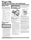
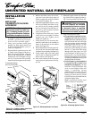
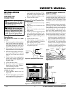
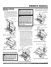
1. Close equipment shutoff valve (see
Figure 26).
2. Pressurize supply piping system by either
using compressed air or opening main gas
valve located on or near gas meter.
Figure 26 - Equipment Shutoff Valve
ON
POSITION
OFF
POSITION
Open
Closed
Equipment
Shutoff
Valve
Pressure Testing Gas Supply
Piping System
Test Pressures In Excess Of 1/2 PSIG
(3.5 kPa)
1. Disconnect appliance with its appliance
main gas valve (control valve) and equip-
ment shutoff valve from gas supply pip-
ing system. Pressures in excess of 1/2
psig will damage fireplace gas regulator.
2. Cap off open end of gas pipe where
equipment shutoff valve was connected.
3. Pressurize supply piping system by ei-
ther using compressed air or opening
main gas valve located on or near gas
meter.
4. Check all joints of gas supply piping
system. Apply mixture of liquid soap
and water to gas joints. Bubbles form-
ing show a leak.
5. Correct all leaks at once.
6. Reconnect fireplace and equipment
shutoff valve to gas supply. Check re-
connected fittings for leaks.
CHECKING GAS
CONNECTIONS
WARNING: Test all gas pip-
ing and connections for leaks
after installing or servicing. Cor-
rect all leaks at once.
WARNING: Never use an open
flame to check for a leak. Apply a
mixture of liquid soap and water
to all joints. Bubbles forming show
a leak. Correct all leaks at once.
INSTALLATION
Continued
Continued
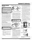
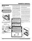
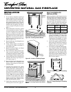
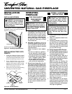
Figure 27 - Checking Gas Joints
Equipment
Shutoff
Valve
Manual Gas Valve
3. Check all joints from gas meter to equip-
ment shutoff valve (see Figure 27). Ap-
ply mixture of liquid soap and water to
gas joints. Bubbles forming show a leak.
4. Correct all leaks at once.
Pressure Testing Fireplace Gas
Connections
1. Open equipment shutoff valve (see Fig-
ure 26).
2. Open main gas valve located on or near
gas meter.
3. Place manual ignition switch in the
OFF position.
4. Check all joints from equipment shutoff
valve to gas valve (see Figure 27). Ap-
ply mixture of liquid soap and water to
gas joints. Bubbles forming show a
leak.
5. Correct all leaks at once.
6. Light fireplace (see Operating Fire-
place, pages 20 through 22). Check all
other internal joints for leaks.
7. Turn off fireplace (see To Turn Off Gas
to Appliance, page 22).
Gas Meter
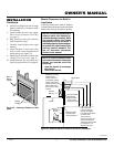
CONVENTIONAL FIREPLACE
INSTALLATION
Conventional installation of fireplace involves
installing fireplace along with corner, face,
or cabinet mantel with hearth base accesso-
ries against a wall in your home. Follow
instructions below to install fireplace in this
manner.
Note:
The instructions below show installa-
tion using the cabinet mantel and hearth
base accessories (see Accessories, page 34).
The hearth base accessory shown is optional
for this installation. You can install fire-
place and cabinet mantel directly on the
floor. The corner mantel accessory cannot
be installed with the hearth bases. You must
install corner mantel directly on the floor.
1. Assemble cabinet mantel, hearth base,
and trim accessories. Assembly instruc-
tions are included with each accessory.
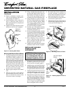
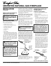
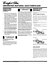
2. When installing blower, install a prop-
erly grounded, 120 volt three-prong
electrical outlet at fireplace location if
an outlet is not there. If possible, lo-
cate outlet so cabinet mantel will cover
it when installed (see Figure 28).
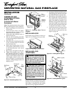
Figure 28 - Placing Hearth Base Accessory
Against Wall
Electrical
Outlet
Hearth
Base
Flexible
Gas Line
Gas Line
Access
Hole