


17
107569
OWNER’S MANUAL
For more information, visit www.desatech.com
INSTALLATION
Continued
Continued
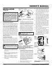
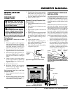
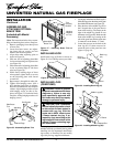
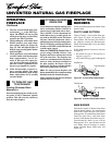
Figure 34 - Attaching Fireplace to Wall
Studs
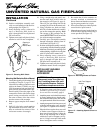
4. Carefully set fireplace in front of rough
opening with back of fireplace inside
wall opening.
5. Attach flexible gas line to gas supply.
See Connecting Fireplace to Gas Sup-
ply, page 14.
6. Plug electrical cord(s) into electrical
outlet installed in step 2.
7. Carefully insert fireplace into rough
opening.
8. Attach fireplace to wall studs using
nails or wood screws through holes in
nailing flange (see Figure 34).
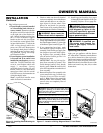
9. Check all gas connections for leaks. See
Checking Gas Connections, page 15.
10. Install brass trim. See Assembling and
Attaching Optional Brass Trim, page 18.
Nailing
Flanges
Nails or
Wood
Screws
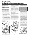
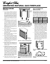
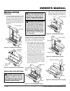
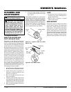
Mantel Clearances for Built-In
Installation
If placing mantel above built-in fireplace,
you must meet minimum clearance between
mantel shelf and top of fireplace opening.
NOTICE: Surface temperatures of
adjacent walls and mantels be-
come hot during operation. Walls
and mantels above the firebox
may become hot to the touch. If
installed properly, these tempera-
tures meet the requirement of the
national product standard. Fol-
low all minimum clearances
shown in this manual.
Supplied Firebox
Hood Must Be
Used at All Times
Wire-mesh
Screen
Firebox
Noncombustible
Material May
Project Off this
Surface above
the Firebox Hood
Mantel Shelf
13" 16" 19" 21"
2
1
/2
"
6"
8"
10"
Note:
All vertical
measurements are
from top of fireplace
hood opening to bottom
of mantel shelf.
These minimum
clearances replace any
other recommended
clearances supplied with
your ANS Z21.11.2
approved gas logs.
Wall board or facing
material (above
firebox) may be of
combustible material,
including decorative
mantel ornaments or
other similar projec-
tions off of the facing
material.
Framing
Material
NOTICE: If your installation does
not meet the minimum clearances
shown, you must do one of the
following:
• raise the mantel to an accept-
able height
• remove the mantel
Figure 35 - Minimum Mantel Clearances for Built-In Installation