


18
107569
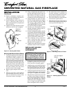
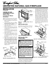
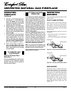
UNVENTED NATURAL GAS FIREPLACE
For more information, visit www.desatech.com
WARNING: Failure to position
the parts in accordance with these
diagrams or failure to use only
parts specifically approved with
this heater may result in property
damage or personal injury.
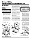
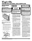
INSTALLING LOGS
(CGEFP33NR)
Each log is marked with a number. These
numbers will help you identify the log when
installing. It is very important to install these
logs exactly as instructed. Do not modify
logs. Only use logs supplied with heater.
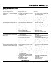
Figure 39 - Installing Back Log (#1)
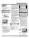
Figure 40 - Installing Middle Log (#2)
CAUTION: After installation
and periodically thereafter, check
to ensure that no flame comes in
contact with any log. With the
heater set to HIGH, check to see
if flames contact any log. If so,
reposition logs according to the
log installation instructions in this
manual. Flames contacting logs
will create soot.
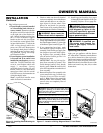
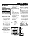
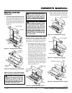
INSTALLATION
Continued
ASSEMBLING AND
ATTACHING OPTIONAL
BRASS TRIM
(Included with Mantel
Accessory)
INote:
The instructions below show assem-
bling and attaching brass trim to fireplace.
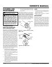
1. Remove packaging from three pieces
of brass trim.
2. Locate four brass screws, two adjust-
ing plates with set screws, and two
shims in the hardware packet.
3. Align shim under adjusting plate as
shown in Figure 36.
4. Slide one end of adjusting plate/shim
in slot on mitered edge of top brass trim
(see Figure 36).
5. Slide other end of adjusting plate/shim
in slot on mitered edge of side brass
trim (see Figure 36).
6. While firmly holding edges of brass
trim together, tighten both set screws
on the adjusting plate with slotted
screwdriver.
7. Repeat steps 1 through 6 for other side.
8. Tighten trim hanging screws (#10 x
6.25 shoulder) into holes in cabinets.
Place the assembled trim onto fireplace
cabinet. Align hanging notches on trim
with hanging screws on side of fire-
place (see Figure 37). Push trim firmly
into place, sliding hanging notches over
hanging screws.
Figure 36 - Assembling Brass Trim
Side Brass
Trim
Top
Brass
Trim
Slot
Mitered Edge
Slot
Shim
Set Screws
Adjusting
Plate
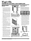
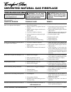
Figure 38 - Installing Hood to Firebox
Figure 37 - Attaching Brass Trim to
Fireplace
Trim
Hanging
Screws
Assembled
Brass Trim
Hanging
Notches
on Trim
INSTALLING HOOD
Install hood to top of firebox as shown in
Figure 38. Use 3 Phillips screws provided.
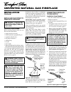
1. Locate pegs on the bottom of back log (#1).
Slide these pegs into the holes in the grate
base behind the burner (see Figure 39).
2. Place the base of the middle log (#2) in
the U-shaped slots of the grate base in
front of the back log. The cutout on the
right of the middle log should fit over
the burner (see Figure 40). Make sure the
front of the middle log is resting on the
tabs of the grate base and the cutout area
is centered over the burner “U” bend.
3. Locate the recesses on the back of the
front log (#3). Fit these recesses be-
tween the posts of the grate base (see
Figure 41, page 19).
Hole in
Grate Base
Back Log
(#1)
Burner
Burner
Tab
Middle Log (#2)
U-Shaped Slot
“U” Bend
Cutout