


105501-01F
For more information, visit www.desatech.com
For more information, visit www.desatech.com
26
OPERATING STOVE WITH BURNER SYSTEM
Operating Optional GWMT1 Wall Mounted Thermostat
INSPECTING BURNERS
Pilot Assembly
Burner Flame Pattern
OPERATING STOVE WITH
BURNER SYSTEM
Continued
OPERATING OPTIONAL GWMT1
WALL MOUNTED THERMOSTAT
Light the burner system as instructed in Lighting Instructions
on page 24. Set wall thermostat to desired temperature.
This thermostat has been electronically calibrated at the factory
and requires no adjustment or leveling.
Upon installation, the thermostat must be allowed to stabilize at
room temperature for a minimum of 30 minutes for proper
operation.
To turn the burner system off, adjust thermostat to the lowest
setting and turn the gas control knob back to PILOT. The pilot
will remain lit.
IMPORTANT:
To turn the pilot off, turn the gas control knob
on the burner system to the OFF position.
WARNING: Do not connect the thermostat to a
power source. Electrical shock and/or a fire hazard
will occur.
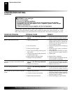
INSPECTING BURNERS
Check pilot flame pattern and burner flame patterns often.
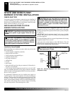
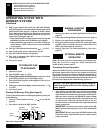
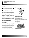
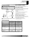
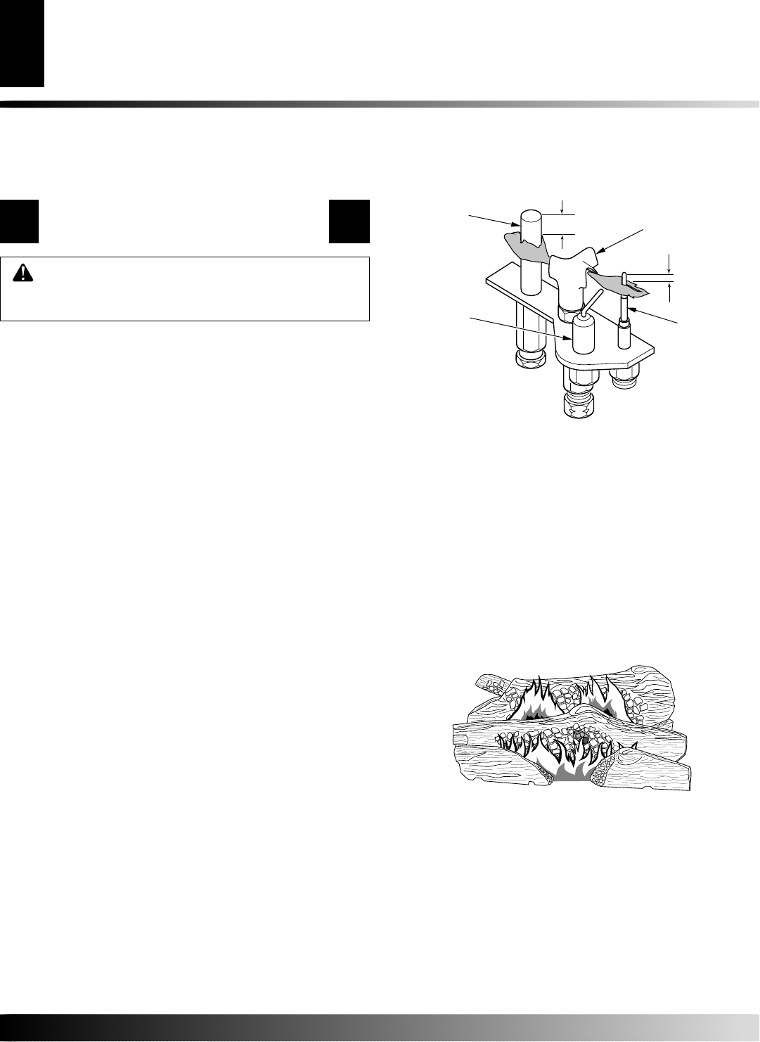
PILOT ASSEMBLY
The pilot assembly is factory preset for the proper flame height.
Alterations may have occurred during shipping and handling. Call
a qualified service person to readjust the pilot if necessary.
The height of the thermopile must be 3/8" to 1/2" above the pilot
flame as shown in Figure 59. The thermocouple must be at a height
of about 1/8" above the pilot flame. The flame from the pilot burner
must extend beyond both the thermocouple and thermopile.
If your pilot assembly does not meet these requirements:
• turn burner system off (see To Turn Off Gas to Appliance, page 25)
• see Troubleshooting, pages 29 through 31
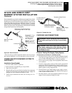
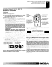
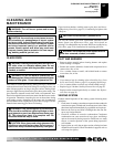
BURNER FLAME PATTERN
Burner flames will be steady; not lifting or floating. Flame patterns
will be different from unit to unit and will vary depending on
installation type and weather conditions.
If the vent configuration is installed incorrectly, the flames will lift
or "ghost". This can be dangerous. Inspect the flames after installa-
tion to ensure proper installation and performance.
Figure 60 shows a typical flame pattern. If burner flame pattern
differs from that described:
• turn burner system off (see To Turn Off Gas to Appliance, page 25)
• see Troubleshooting, pages 29 through 31
Figure 59 - Pilot Assembly
Figure 60 - Typical Flame Pattern
Thermopile
Pilot Burner
Thermocouple
Piezo Ignitor
1/8"
3/8" to 1/2"