


105501-01F
For more information, visit www.desatech.com
For more information, visit www.desatech.com
16
Cathedral Ceiling Installation
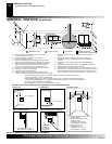
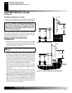
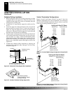
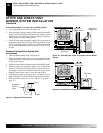
1. Remove shingles or other roof covering as necessary to cut the
rectangular hole for the support box. Mark the outline of the
cathedral ceiling support box on the roof sheathing using the
locating hole as a center point.
2. Cut the hole 1/8" larger than the support box outline (see Fig-
ure 32).
3. Lower the support box through the hole in the roof until the
bottom of the box extends at least 2" below the ceiling (see
Figure 32). Align the support box vertically and horizontally
using a level. Temporarily tack the support box in place through
the inside walls and into the roof sheathing.
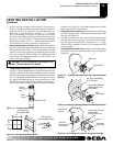
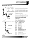
4. Using tin snips, cut the support box from the top corners down
to the roofline and fold the resulting flaps over the roof sheath-
ing (see Figure 33). Apply a bead of non-hardening mastic
around the top edges of the support box to make a seal be-
tween the box and the roof. Nail in place with roofing nails.
Remove any combustible material that might be inside of the
support box.
5. Complete the cathedral ceiling installation by following the
same procedures outlined in steps 2 through 7 for Flat Ceiling
Installation, page 15
.
VENTING INSTALLATION
Continued
Vertical Termination Configurations
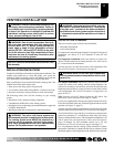
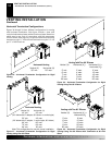
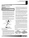
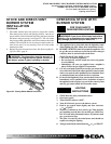
Figures 34 and 35 and Figures 36 and 37 on page 17 show four
different configurations for vertical termination. All connections
must be sealed with high temperature silicone sealant as specified
in the second warning statement on page 11.
VENTING INSTALLATION
Installation For Vertical Termination (Cont.)
Figure 32 - Cathedral Ceiling Support Box Installation
Nonhardening Mastic
under all edges of support
box before nailing
Figure 33 - Installed Cathedral Ceiling Support Box
Cut hole 1/8" larger than support
box when projected onto roofline
2" minimum
below finished
ceiling
Cathedral ceiling
support box
Level
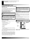
Venting with Two 90° Elbows
Vertical (V) Horizontal (H
1
) +
Horizontal (H
2
)
5' min. 2' max.
6' min. 4' max.
7' min. 6' max.
8' min. 8' max.
20' max. 8' max.
Figure 35 - Vertical Rigid Venting Configuration Using Two 90°
Elbows with Two Horizontal Runs
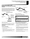
Venting with One 90° Elbow
Vertical (V) Horizontal (H)
5' min. 2' max.
6' min. 4' max.
7' min. 6' max.
8' min. 8' max.
20' max. 8' max.
Figure 34 - Vertical Rigid Venting Configuration Using One 90°
Elbow
Note:
Install
restrictor into 4"
collar of burner
system as shown.
Note:
Install
restrictor into 4"
collar of burner
system as shown.