


105501-01F
For more information, visit www.desatech.com
For more information, visit www.desatech.com
11
11
WARNING: Read all instructions completely and
thoroughly before attempting installation. Failure to
do so could result in serious injury, property damage
or loss of life. Operation of improperly installed and
maintained venting system could result in serious
injury, property damage or loss of life.
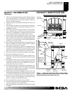
WARNING: Seal all vent connections. Seal only
the outer pipe connections with high temperature
silicone (600°F/316° C). Before joining elbows and
pipes, apply a bead of high temperature silicone
sealant (GE RTV 106/Loctite RTV 81585) to the male
end of the elbow or pipe. High temperature silicone
must also be used to re-seal any connections after
maintenance to venting system.
NOTICE: Failure to follow these instructions will void
the warranty.
INSTALLATION PRECAUTIONS
Consult local building codes before beginning the installation. The
installer must make sure to select the proper vent system for
installation. Before installing vent kit, the installer must read this
stove and burner system manual and vent kit instructions.
Only a qualified service person should install venting system. The
installer must follow these safety rules:
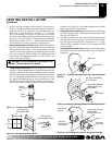
• Wear gloves and safety glasses for protection
• Use extreme caution when using ladders or when on roof tops
• Be aware of electrical wiring locations in walls and ceilings
The following actions will void the warranty on your venting
system:
• Installation of any damaged venting component
• Unauthorized modification of the venting system
• Installation of any component part not manufactured or approved
by DESA International
• Installation other than as instructed by these instructions
VENTING INSTALLATION
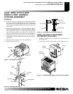
WARNING: This stove with burner system and
vent assembly must be vented directly to the outside.
The venting system must NEVER be attached to a
chimney serving a separate solid fuel burning appli-
ance. Each gas appliance must use a separate vent
system. Do not use common vent systems.
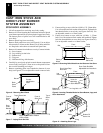
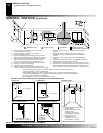
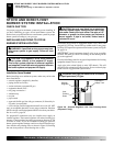
WARNING: Horizontal sections of this vent sys-
tem require a minimum clearance of 2" from the top
of the pipe and 1" minimum to the sides and bottom.
Vertical sections of this system require a minimum of
1" clearance to combustible materials on all sides of
the pipe.
INSTALLATION PLANNING
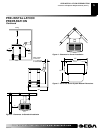
There are two basic types of direct-vent installation:
• Horizontal Termination
• Vertical Termination
It is important to select the proper length of vent pipe for the type of
termination you choose. It is also important to note the wall
thickness.
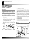
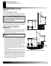
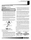
For Horizontal Termination: Select the amount of vertical rise
desired. The horizontal run of venting must have 1/4" rise for every
12" of run towards the termination.
You may use one or two 90° elbows in this vent configuration. See
Horizontal Termination Configurations on page 14.
WARNING: Never run the vent pipe downward as
this may cause excessive temperatures which could
cause a fire.
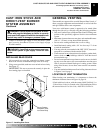
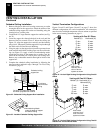
For Vertical Termination: Measure the distance from the burner
system flue outlet to the ceiling. Add the ceiling thickness, the
vertical rise in an attic or second story, and allow for sufficient vent
height above the roofline. You may use one or two 90° elbows in this
vent configuration. See Vertical Termination Configurations on
pages 16 and 17.
Note:
You may use two 45° elbows in place of a 90° elbow. You
must follow rise to run ratios when using 45° elbows.
For two-story applications, firestops are required at each floor level.
If an offset is needed in the attic, additional pipe and elbows will be
required (see Figure 31, page 15).
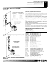
You may use a chase with a vent termination with exposed pipe on the
exterior of the house. See Installing Vent System in a Chase, page 12.
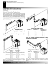
Your Comfort Glow stove with direct-vent burner system has been
tested for a maximum 17" wall thickness when using a 60º elbow
directly off the back of the stove. The maximum horizontal run is 20'
with 8' vertical rise (see Installation for Horizontal Termination,
pages 12 through 14). The maximum vertical run is 30' (see
Installation for Vertical Termination, pages 15 through 17).
It is very important that the venting system maintain its balance
between the combustion air intake and the flue gas exhaust. Certain
limitations apply to vent configurations and must be strictly followed.
VENTING INSTALLATION
Installation Precautions
Installation Planning